21st Century Reciprocating Compressors for Downstream Applications

Greg Phillippi, Ariel Corporation
Published by Hydrocarbon Engineering
Technology, like time, marches on. Think about the advancements in technology that have taken place in the last 50 years. Advancements have taken us from punch cards to medical computers that can be swallowed. Telecommunication has gone from rotary dial to cell phones. Most advancements led to smaller, less expensive means to do the same thing. It begs the question, why do some industry standards and the people who write them refuse to acknowledge proven technologies that are as reliable but less expensive than those used 50 years ago? Take the reciprocating compressor industry as an example.
For nearly 100 years, reciprocating compressors used in downstream oil and gas industry (process) applications have utilized long strokes and low rotating speeds. Virtually all have been block mounted and equipped with compressor cylinder liners and provision for cooling supported since 1964 by American Petroleum Institute Standard 618 "Reciprocating Compressors for Petroleum, Chemical, and Gas Industry Services."
Today alternate designs are available, offering the industry equal reliability at lower capital cost. Several manufacturers offer designs with shorter strokes, in the 76 to 229 mm (3 to 9 inch) range, with rotating speeds varying from 600 to 1000 rpm. These modern designs are packaged into complete compression system modules contributing to reduced capital cost through reduced installation time and therefore cost. Many of these modern designs omit liners and provision for cooling as required by API Standard 618 further reducing cost.
Very early reciprocating compressors had strokes in the range of 914 mm (36 inches) or longer, had rotating speeds that today would be considered to be very low, in the range of 100 rpm, and were derived from steam engine technology. Over time the rotating and average piston speed increased as the sealing technology for piston rod packing and piston rings improved. For example, very early piston rod packing was called a "stuffing box" because it was a cylindrical cavity surrounding the piston rod filled (stuffed) with coiled rope to create a seal. This "stuffing box" was derived from steam engine technology. Over time the packing became much more sophisticated developing into the segmented packing ring sets made of various metallic and non-metallic materials so common today.
There is end-user interest to increase rotating and piston speed because increases in both lead to reduced capital cost. Increases in rotating and piston speed reduce the physical size of the machine resulting in less mass and therefore less cost. Today, the vast majority of downstream process reciprocating compressors are driven by electric motors, which have their cost decrease as their rotating speed increases. So an increase in rotating speed decreases the cost of both of the compressor and the driver.
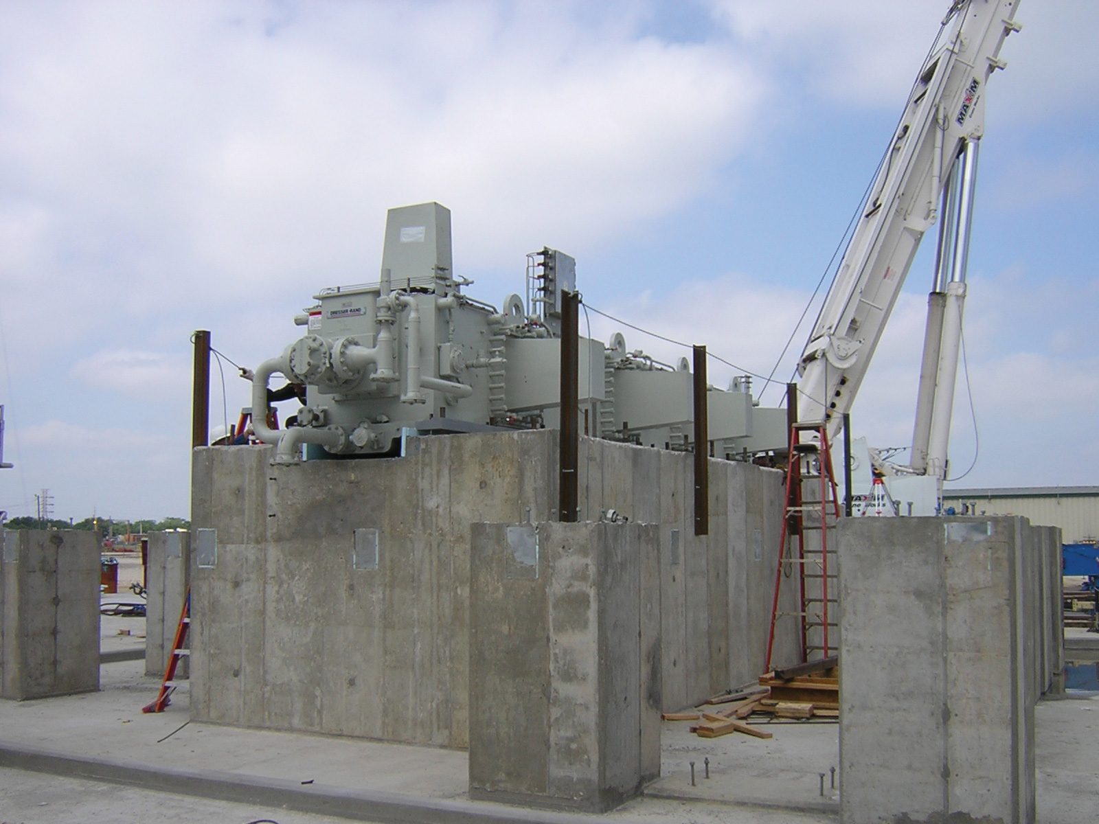 Figure 1: Large block mount low speed long stroke compressor during construction at site.
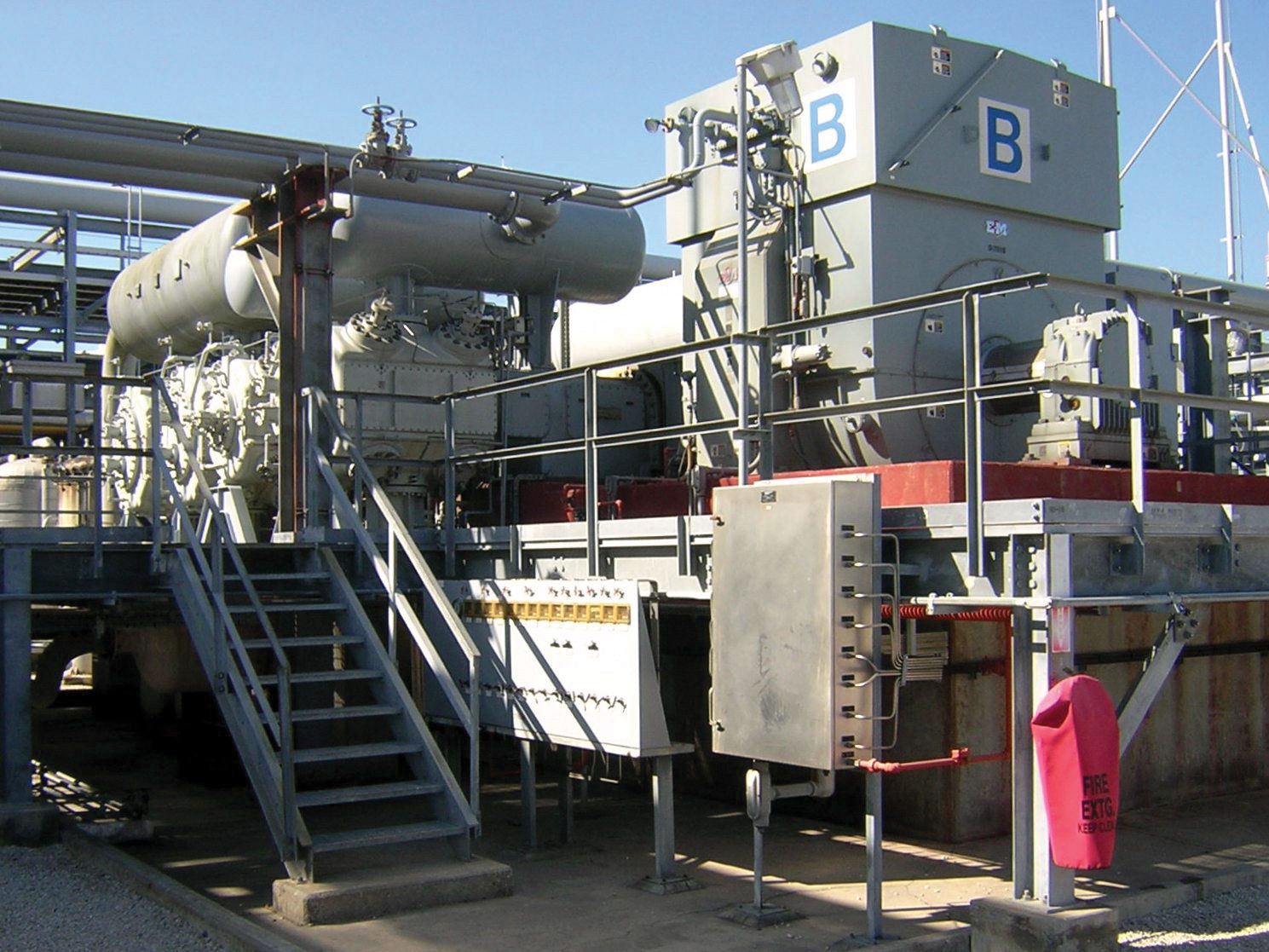 Figure 2: Large block mount low speed long stroke compressor in operation.
Bock Mount Versus Packaged
The physical size of the typical long stroke (305 to 508 mm, 12 to 20 inch) low speed (250 to 500 rpm) compressor, as shown in Figures 1 and 2, lends itself to being stick-built at the site (block mounted) rather than packaged into a module in a fabrication facility. Most of the reciprocating compressors that exist today in refineries and petrochemical facilities are block mounted, meaning bare compressors are built in a factory, shipped to the installation site, assembled or disassembled (depending on size and shipping restrictions), and installed on a large concrete foundation (the "block," see Figure 1). After which, all the supporting systems, such as pulsation bottles, separators, process and utility piping, lubrication systems, driver, coupling, instrumentation, and control system, are installed. Long-stroke low-speed compressors lend themselves to this manner of installation because they are typically very large and heavy.
Modern short-stroke medium speed compressors lend themselves to being packaged (as shown in Figure 3) as they are smaller and lighter for the same capacity. A compressor package is a complete gas compression system module having the compressor with its driver, coupling, all process gas, and utility piping, lubrication systems, and all the instrumentation and control systems mounted on a structural steel skid. This skid serves as a platform on which to mount all the previously mentioned equipment, but also, in many instances, the compressor's foundation.
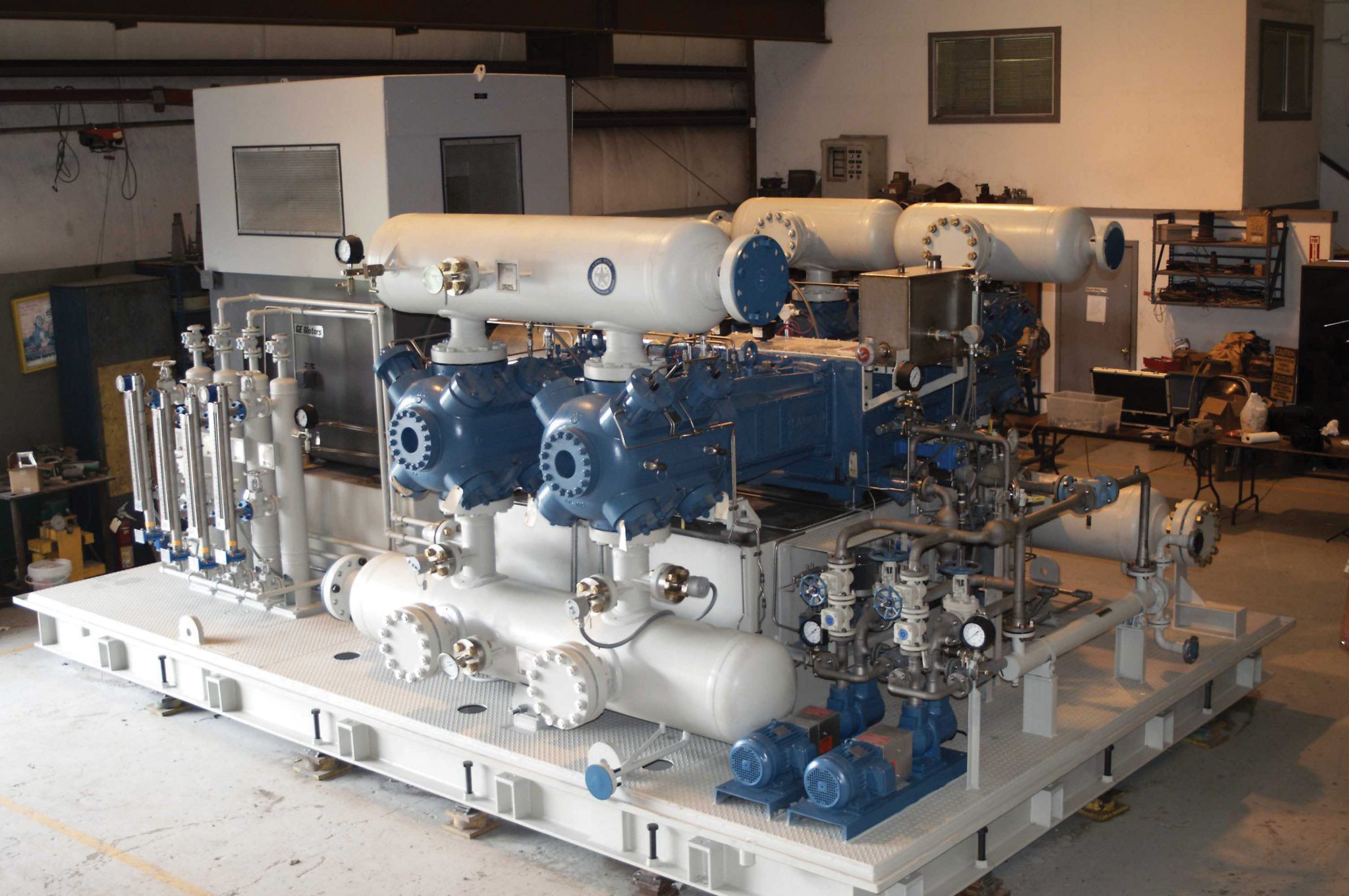 Figure 3: Packaged medium speed short stroke compressor.
Lined Versus Unlined
API Standard 618 requires compressor cylinders to have liners. Fundamentally, liners are included only for commercial reasons. A liner is not a part required for a compressor cylinder to be able to compress the gas. The reasons a liner may be used include:
- A liner can be a lower cost replaceable wear element in a compressor cylinder assembly where a bare replacement cylinder body might be very expensive with a long lead time relative to the cost and lead time of a replacement liner.
- A liner can be made of suitable wear material, such as gray iron, when the cylinder body is made of an unsuitable wear material. An example of such an unsuitable material is ASTM A395 "Standard Specification for Ferritic Ductile Iron Pressure-Retaining Castings for Use at Elevated Temperatures," the material API 618 requires to be used for cast ductile iron cylinder bodies. ASTM A395 happens to be a very poor material for use in an application that subjects the material to rubbing wear, as is the case in a cylinder bore where the piston and piston rings, or the wearbands and piston rings, are rubbing against it. Consideration must be given to protect A395 ductile iron material, and a liner is only one way to accomplish that.
- Utilization of a liner allows the cylinder bore diameter to be changed rather easily.
One of the major reasons why liners are not utilized in short-stroke cylinders is the liner's effect on the cylinder's capacity capability. This is a technical issue that leads to significant commercial harm. The following chart, Figure 4, will help to explain.
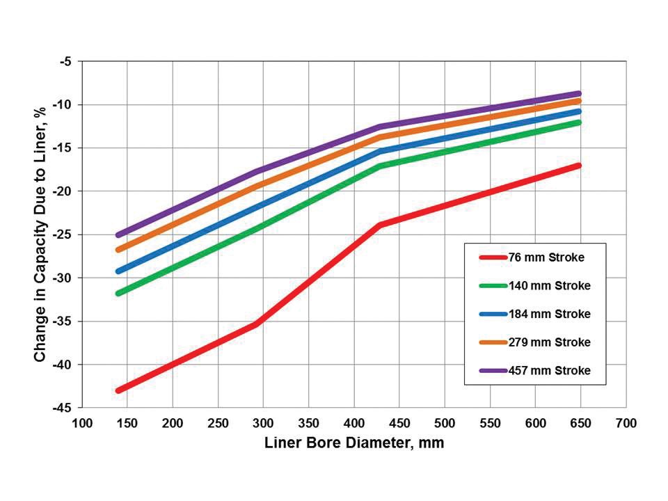 Figure 4: Chart showing change in capacity capability due to the addition of a liner.
A liner adds fixed clearance, which reduces capacity. This capacity reduction can be substantial in shorter stroke cylinders. The addition of the liner also reduces piston displacement, which, when combined with the effect of the additional fixed clearance, results in a significant reduction in a cylinder's capacity capability. Figure 4 chart takes both into account. For example, consider a 300 mm liner bore diameter (11.8 inches, "300" on the horizontal axis). This is actually a 325 mm (12.8 inches) diameter bore cylinder with a 12.5 mm (0.5 inches) thick liner installed. The capacity capability has been reduced from that of a 325 mm bore cylinder to that of a 300 mm. Also, the addition of the liner has increased the fixed clearance volume, which reduces the volumetric efficiency, further reducing the capacity capability. For the 300 mm liner bore example, this capacity capability reduction is on the order of 35 percent for 76 mm (3 inches) stroke. It is still significant for a 457 mm (18 inches) stroke at about a 17 percent reduction. The chart assumes a compression ratio of 2.5 and a gas adiabatic exponent of 1.4. Assumed liner thickness is 9.5 mm (0.375 inches) up to 254 mm liner bore (10 inches) and 12.5 mm (0.500 inches) 254 mm bore (10 inches) and larger following API Standard 618 guidelines.
For a given required compressor capacity, the addition of a liner requires a larger compressor by the percentage shown in the chart. Again referring to the 300 mm example, a 76 mm stroke compressor would have to be about 35 percent larger if equipped with a liner. So an end-user is buying a compressor about 35 percent larger just to have it equipped with lined cylinders.
While a liner provides one method of protecting A395 ductile iron from wear, other methods exist. Another possibility is to harden the unlined cylinder bore to improve the wear characteristics. One proven hardening method uses the ion-nitride heat treat process. A full explanation of the process is beyond the scope of this article. Still, it results in hardness at the surface of the A395 ductile iron of approximately 55 Rockwell C. It provides substantial case depth with a hardness of approximately 30 Rockwell C at a depth of 0.15 mm (0.006 inches).
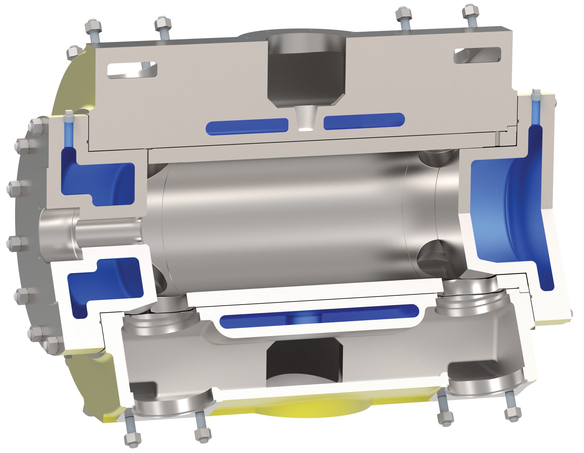 Figure 5: Drawing of a cylinder body with a liner and cooling jacket.
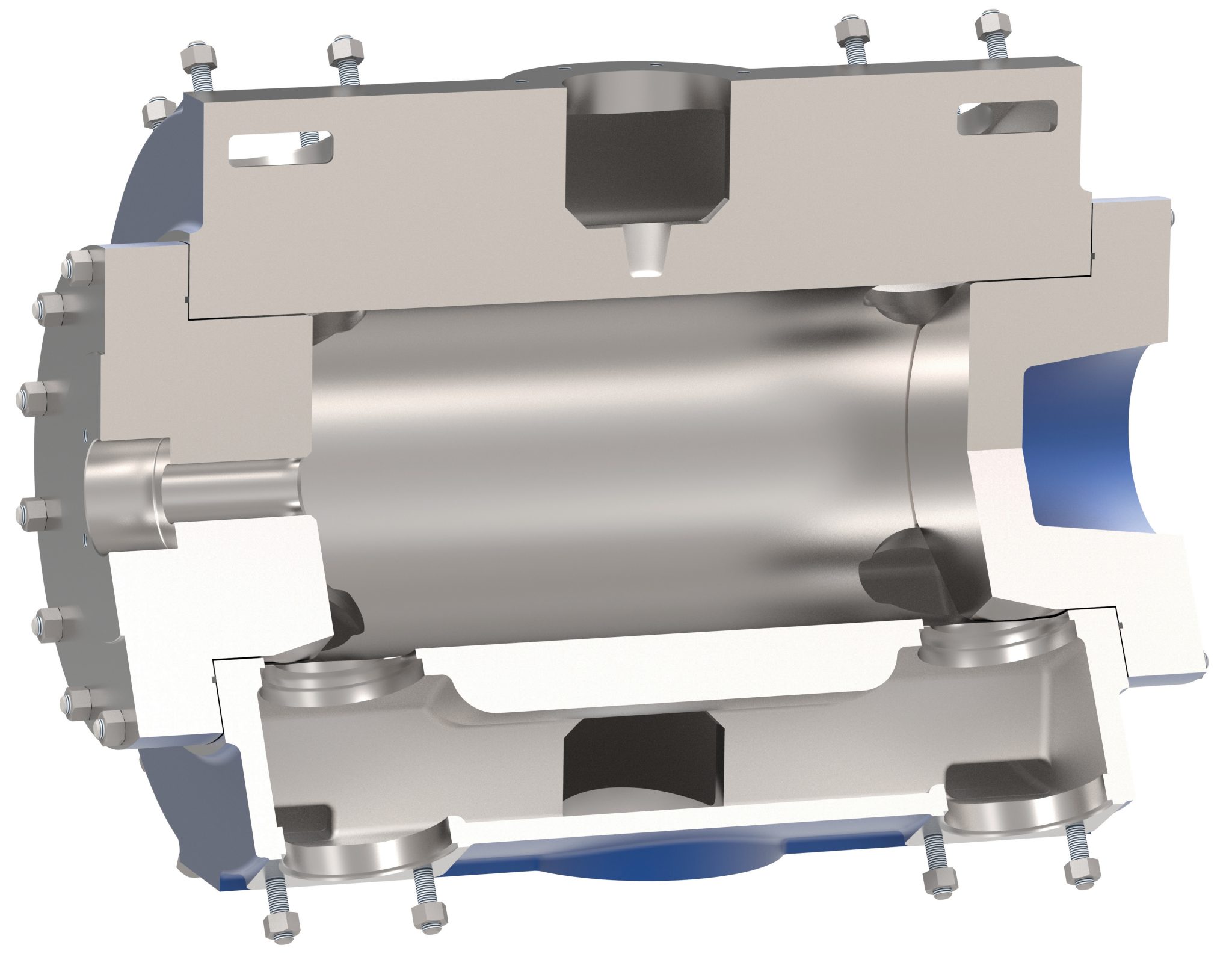 Figure 6: Drawing of cylinder body without a liner ore cooling jacket.
Cooled Versus Non-cooled
API Standard 618 also requires compressor cylinders to have provision for cooling. Figure 5 is a cylinder with a liner, and a cooling jacket, and Figure 6 is a cylinder without a liner or a cooling jacket. Like liners, cooling is not required for a compressor cylinder to compress the gas.
API Standard 618 mentions one instance where provision for cooling may be beneficial. It mentions "when cylinders are operated while unloaded for extended periods of time." This refers to the situation when it may be required or beneficial to operate a double-acting cylinder with both the head and crank ends deactivated at the same time. The standard requires that a forced liquid coolant system be used when cylinders may be required to operate fully unloaded. And it is correct that in some situations, the cooling system may have the capacity to remove enough of the parasitic heat generated when the gas washes in and out of the head and crank end compression chambers to allow "operation fully unloaded for extended periods of time." It is not a given that every compressor cylinder incorporating forced liquid coolant can operate fully unloaded for an extended period as the cooling system may not be capable of removing enough parasitic heat, potentially causing piston ring, wearband, and compressor valve premature wear or failures.
When discussing the cooling requirement, end-users and manufacturers will often mention the need to use the cooling jackets as heaters. The cooling jackets will be used to heat the cylinders prior to startup to avoid liquid condensing out of the gas stream (warm saturated gas contacting cold metal) and causing damage to the compressor valves or other components when the compressor starts. While this certainly works and can be a valid reason for using cylinders with cooling (heating?) jackets, not every application encounters this issue, and it's not the only way to start a compressor to avoid this condensation.
Non-cooled cylinders have been used with success in the upstream natural gas industry for 50 years and the downstream industry for 20 years. There can be no question that the technology works, especially considering that almost every manufacturer offering reciprocating compressors to the upstream and midstream markets has models utilizing non-cooled cylinders, with one having shipped over 150,000.
The benefits to end-users of non-cooled cylinder technology include:
- Less capital cost as there is no cylinder jacket water system to buy.
- Less operation and maintenance cost. There is no cylinder jacket water system to operate or maintain.
- Higher quality compressor cylinder bodies. Non-cooled cylinder body castings are of significantly higher quality due to the fact there is no cooling jacket complicating the casting. This also means there is a reduced chance of a future structural failure.
Conclusion
Short stroke medium speed reciprocating compressors utilizing unlined and non-cooled compressor cylinder technology represents the newest technology and are the "21ST-century reciprocating compressors for downstream applications". These compressors dominate the upstream and midstream oil and gas industries and are becoming more common and gaining wider acceptance downstream.
However, many downstream end-users have been reluctant to consider short-stroke higher speed compressors primarily because of concerns about reliability. Many find it difficult to understand how a higher speed reciprocating compressor can have equal reliability to a low speed, but it is possible and being proven every day. An example is two 4.1 MW (5500 horsepower) 146 mm (5.75 inch) stroke 713 rpm packaged compressors operating in a hydrogen product application in a hydrogen plant in the United States Gulf Coast area. Both have achieved over 24,000 hours of uninterrupted operation and are scheduled for an overhaul at 32,000 hours. This is exactly the type of success being achieved with this 21ST-century technology.Although the basic design of a reciprocating compressor has not changed much over the years, manufacturing, design capabilities, non-metallic materials, and performance modeling have. Modern reciprocating compressors are capable of higher rotating and piston speeds without compromising reliability. To paraphrase an ad from a United States automobile manufacturer, "these are not your father's reciprocating compressors".