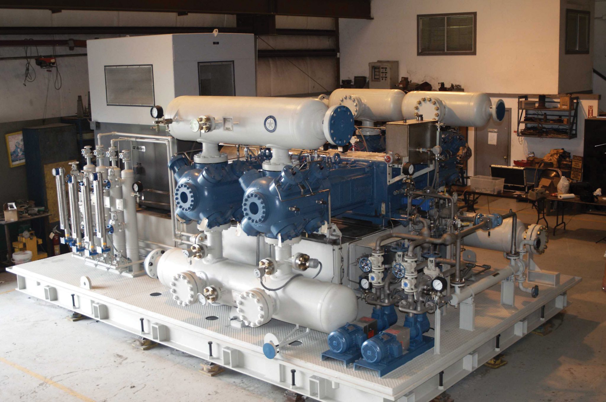
Using Design Principles for Troubleshooting Compressors
Let’s walk through a design session. This section will give you some insight into the relationships, and often compromises, that govern the design process. You can then apply these relationships to dig up the root of compressor problems.
Understanding Basic Design Relationships
Before jumping into the engineering world, a few important physical relationships must be understood.
The Ideal Gas Laws
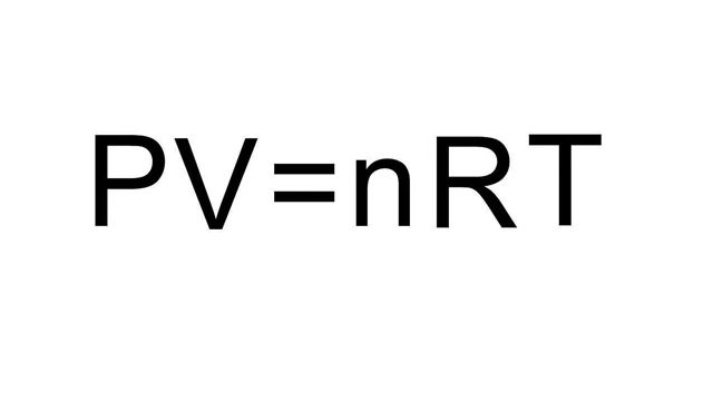
Three things have to be calculated and controlled during the compression process -- pressure, volume, and temperature. These three characteristics of gases have a close relationship to one another. By keeping one of them constant, the other two will have either a direct or inverse proportion. These ideal gas laws are:
- Boyle’s Law states that when temperature is kept constant and volume is decreased, pressure will increase.
- Amonton’s Law states that when volume is kept constant and temperature is increased, pressure also increases.
- Charles’ Law states that when pressure is kept constant and temperature is increased, volume also increases.
Defining the Standard Cubic Foot When we measure the volume of gas in a compressor, we have to use a standard that will apply at all atmospheric pressure conditions. The ambient air pressure on the beach in Galveston, Texas will be significantly higher than that in a Denver, Col., snowstorm. Part of the difference can be attributed to the relative altitude of both locations above sea level. The remaining difference relates to relative temperature. It’s a safe bet that the beach is going to be a bit warmer.
A few hundred years ago the Standard Cubic Foot was defined as a standard for measuring gas volume. The conditions set forth were close to the Galveston beach in winter. If we are sitting on a beach and the current temperature is 60 ° F, we probably won’t be going swimming. So now we can focus on business, right? At these temperature and pressure conditions, if we placed an open box on the beach that measured one cubic foot in size, then closed the lid – we would have a Standard Cubic Foot of air in the box. By definition, the conditions needed to create a Standard Cubic Foot of air are 60 ° F ambient temperature and 14.7 PSI ambient pressure.
The Actual Cubic Foot versus the Standard Cubic Foot
Now that you’ve enjoyed your trip to the beach, let’s talk about real-world conditions. If we took our box of beach air and pushed the lid half of the way into the box without letting any air escape, the volume of air in the box is now 1/2 of an Actual Cubic Foot. The volume of air in the box, however, is still 1 Standard Cubic Foot. The difference is now that same gas has 1/2 of the actual volume it had and the pressure and temperature have increased. The only time the Actual Cubic Foot and Standard Cubic Foot measurements for a gas will be the same is when the ambient conditions are 60 ° F and 14.7 PSI.
Why Knowing Temperature and Pressure of the Gas at each Stage is Important
If we combine the ideal gas laws and the concept of the standard cubic foot, we can calculate the temperature, pressure, and volume of a gas as it moves through a compressor without the need to sit on a beach and squeeze a box. Although the beach trip may sound like fun, calculating what a compressor will do before building it certainly saves a lot of time and money.
A Compressor Design Example
This example guides you through the typical steps in the compressor design process. If you know how a machine is designed to meet the desired output, it will help you find out why it is no longer meeting the desired output after it’s operational.
Step 1 - Determining the Overall Compression Ratio
We start the design process by calculating the overall compression ratio from the inlet and discharge pressures for the system. Let’s suppose we will have an inlet gauge pressure of 100 lbs. and want a final output gauge pressure of 1000 lbs. The obvious answer is to divide 1000 by 100 and declare the overall compression ratio as 10. Wrong. Remember that the numbers quoted were gauge pressures. We have to work in absolute pressures. That means adding atmospheric pressure (14.7 lbs. at sea level - correct this for your location) to the gauge pressures. After correcting for atmospheric pressure and dividing the final pressure by the inlet pressure, we get an overall compression ratio of 8.84.
In practical applications, the overall compression ratios are fairly standard. Gas gathering applications will limit compression ratios to between 2.4 and 4.0 per stage. Compressed Natural Gas (CNG) applications start at 5 lbs. and move up to 4600 lbs. Pipeline applications, on the other hand, use very low compression ratios between 1.05 and 1.2 in a single-stage unit. No matter what the application is, calculating the overall compression ratio is the first step in the design process.
Step 2 - How Many Stages in the Unit?
There are many factors that limit the maximum compression ratio a single stage can deliver. The most important are probably rod load and gas temperature. Reasons for trying to limit the number of stages include maximizing drive efficiency (size / power of the drive unit required) and minimizing the cost of peripheral equipment (intercoolers, scrubbers, control and monitoring equipment, etc.)
Let’s continue our example from the previous step. The overall compression ratio is 8.84. Given the volume and temperature limits of the gas mix we are handling, we will need a multistage unit. So we need to calculate the compression ratio each stage will have to handle. If we use a two-stage system, we take the square root of the overall compression ratio. The square root of 8.84 is 2.97. For a three-stage unit we take the cube root of 8.84, which is 2.06. For successive numbers of stages we take the nth root of the overall compression ratio where n is the number of stages.
In this application, a compression ratio of 2.97 for each stage is within design limits. Even though our two-stage system will probably have the same number of cylinders as a three-stage system, we are eliminating a complete set of intercoolers, scrubbers, and control circuitry by using a two-stage setup. If temperature was a major concern, a three-stage unit would have lower operating temperatures (and lower rod loads), but would cost more to purchase and operate.
Step 3 - Calculating Gas Temperatures
Keeping temperatures consistent throughout the unit is crucial to ensuring balanced operation. When we computed the overall compression ratio for the unit, we used absolute pressure. In order to measure thermal characteristics accurately, we have to use absolute temperature. The Fahrenheit scale is normally used to measure room temperature. But absolute temperature is measured using the Rankine scale. Rankine temperature is computed by adding 460 to the Fahrenheit temperature. This scale is used because all design and gas law equations depend on temperature measured in the absolute scale.
Now we find the suction temperature for each stage. The suction temperature and compression ratios for each stage are used along with the n value of the gas to compute various characteristics of the discharge. The n value is a numeric constant that is specific to every gas compound. These constants are listed in most mechanical engineering reference books. The n value represents the ratio of specific heats for a gas. This ratio helps describes the volume of a gas at different temperature and pressure conditions. Being able to compute the volume of the discharge gas in a compressor stage is critical when sizing the cylinders in the next stage. If you don’t know the volume of the inlet gas you need to compress, you can’t determine the cylinder size for the stage.
Step 4 - Determining Horsepower and Frame Size
By this point in the design process we have already made several important decisions. The overall compression ratio is 8.84 which will move 100 lbs. inlet pressures up to our desired 1000 lbs. discharge pressure. We will use a two-stage unit with a 2.94 compression ratio across each stage. This information is sufficient to compute the horsepower requirements for the drive unit. After the drive unit size is determined, we can pick a frame for the compressor unit.
Step 5 - Determining Desired Flow Rate
Flow rate is sometimes expressed in the number of cubic feet per day the unit can compress. What does a daily flow rate really mean? Let’s return to our sunny beach in Galveston. Suppose we have a giant balloon that holds 1.25 million cubic feet of gas. Okay, so pretend it doesn’t block out the sun and let’s move on. If we hook a compressor up to the balloon and switch it on, the time it takes to drain the balloon will tell us the flow rate of the compressor. If the balloon is drained in 24 hours, the compressor has a 1.25 million cubic foot per day flow rate. If it drains in 12 hours, the unit has a 2.5 million cubic foot per day flow rate.
Most compressor specifications are quoted in Standard Cubic Feet per minute instead of per day. Hence the common shorthand of SCFM. If you have to convert a daily rate to a minute rate, simply divide by 1440 (60 minutes per hour multiplied by 24 hours per day).
Compressor bore sizes are not measured in feet, however, they are measured in inches. So we also need to convert the number of cubic inches in the bore into cubic feet before expressing the volume of gas output. That figure tells us approximately how much volume each stroke of the piston supplies. By multiplying this volume by the RPM of the crankshaft we can determine the output of the cylinder per minute. Double-acting cylinders require the addition of crank-end displacement to head-end displacement, then multiply this number by the RPM to determine the output of the cylinder per minute.
Step 6 - Calculating Piston Displacement
Computing the flow rate from a cylinder was pretty simple, right? Now reality strikes. Several factors dictate that the discharge from a cylinder is never equal to its total displacement. The piston never completely reaches the end of the cylinder bore. This clearance space reduces the cylinder output volume because not all the gas in the cylinder is forced out. Another factor that reduces efficiency is the distance the piston has to retreat into the cylinder before the inlet valve opens letting in more gas for the next compression stroke. These factors, along with several other less important ones, combine to create a number called volumetric efficiency. You have to apply the volumetric efficiency factor of a cylinder to the ideal output volume in order to compute actual output volume.
In our design example we have to use a 115.53 actual cubic foot per minute flow rate to compensate for temperature and pressure conditions at seal level and 80 ° F (more of a realistic average temperature for Galveston) in order to get the 100 lbs. desired rate. Volumetric efficiency further reduces the flow rate and the final piston displacement needed is 144.4 cubic feet per minute. Now we can pick out a JGA frame from the Ariel databook where all this information is listed. We will base our flow rate on a drive speed of 1800 RPM. You will see that the databook lists a headend and crankend displacement. This is simply the piston diameter multiplied by the stroke. Add these two numbers and look at the included charts for the 144 cubic feet per minute piston displacement that we need.
Step 7 - Sizing the Second Stage
We sized the first stage cylinder by knowing the volume of the gas it had to compress. Before we can size the second (or any other) stage, we need to compute the volume of the gas coming out of the previous stage. Thanks to our ideal gas laws, we can find the volume of gas coming out of the first stage by using the pressure of the gas. And we know the pressure. We can determine the pressure by multiplying the first stage inlet pressure by the first stage compression ratio. Since our compression ratio for both stages is 2.97 and the inlet pressure is 114.7 lbs. (don’t forget to add the 14.7 lbs. of atmospheric pressure to the 100 lbs. of gauge pressure), our outlet pressure will be 340.6.
To double-check our final output pressure from the second stage we multiply the compression ratio for the second stage of 2.97 by the inlet pressure of 340.6. This gives us a final output pressure of 1011.5. This is sufficiently close to our desired pressure of 1014.7. Now we use our ideal gas law formula to compute the volume of gas at the second stage inlet. This is 41.78 actual cubic feet per minute. If we apply the correction factors, including volumetric efficiency, we come up with an inlet volume of 52.2. We can then use the Ariel databook to find the correct piston displacement for this inlet volume. In this application, we would use a JGA/2 with a 6-1/8 inch headend and 3-3/8 inch crankend. Now the compressor has been sized according to operating requirements.
Applying the Design Techniques to Find a Problem
In this scenario, we’ll examine a problematic two-stage compressor unit. The original output pressure of the second stage was 360 lbs. It has dropped to 300 lbs. In the first stage, output pressure and temperature have increased. This could happen over a period of weeks, but if it happened gradually enough and you hadn’t been recording the output levels, it would have gone unnoticed. The pressure levels tell you where to look for a problem because when a compressor cylinder has a problem, it moves less gas. In a multi-stage unit, the problem stage will usually be the only one whose output pressure increases. The successive stages between the problem stage and the final output will have a net pressure drop. In our case, the first stage is most likely the problem since its output pressure increased while the second stage pressure dropped.
In single-stage units, or units where there is little pressure change, you will have to rely strictly on temperatures to find the problem stage or area. In our scenario, the pressure and temperature of the first stage output have increased. Since our temperature and pressure rose while the overall compression ratio went down, we have a leaking discharge valve. As the piston retreats to pull in more inlet gas, the hot discharge gas also invades the cylinder. This explains our increased temperatures and pressures in the first stage outlet. The second stage output has less pressure since it is losing inlet volume to the first stage through the valve leak.
By understanding the design process, which attempts to balance the compression ratios across all stages, you can easily compute what the compression ratio for each stage is by knowing the overall compression ratio. Divide the final output pressure by the inlet pressure. This gives you the overall compression ratio. Then take the nth root of the overall compression ratio where n is the number of stages. Then multiply the inlet pressure (corrected for atmospheric pressure) by the first stage compression ratio. Using this as an approximation for the outlet pressure, continue using this method to determine the inlet and output pressures for each stage. Now you can use gauge pressures to guide the way to the problem stage. Temperatures can also indicate a problem. Temperature may be the only tool you have on low compression or single-stage applications.