Lube Reduction in Reciprocating Compressors
Authored by: Justin Yance & Joe Hagan - Ariel Corporation, Mount Vernon, Ohio, USA
Abstract
Tens of thousands of reciprocating compressors operating in North America each consume as much as $250,000 per year in lubricating oil. In general, most of these compressors are consuming more oil than necessary, so operating costs could be significantly reduced. Cost reduction can be achieved with relatively simple steps to ascertain the correct type and quantity of oil being delivered to each lube point, without changing the designs or materials of the wearing components. This paper describes the established method, as well as steps to ensure the lube system is operating correctly, to provide long-term reliable compressor operation.
Introduction
Maintaining proper lubrication on reciprocating gas compressors is imperative to equipment reliability. Compressors most often operate continuously which accumulates considerable runtimes on wearing components. Reciprocating compressors rely upon two lubrication systems that deliver oil to critical components in the drivetrain, cylinders, and packings. The first is a recirculating system which protects bearings, bushings, thrust plates, and crossheads in the drivetrain. The second system is a “total-loss” system which provides oil to the cylinder bore, piston rings, piston rod, and packing rings. The major difference between these two systems is how the oil is used. The drivetrain reuses its oil many times before this fluid is replaced. A cylinder lube system only uses its oil once before the oil is consumed in the compression process. Making efficient use of oil within the cylinder lubrication system is key when minimizing operating costs while maximizing equipment reliability. This paper presents the established method for maintaining the cylinder lubrication system and determining appropriate lubrication rates.
The cylinder lubrication system, also known as the “force-feed” system, uses a positive displacement plunger pump to feed oil to a divider valve which proportions the oil to critical areas within the cylinder and packing. The flowrate of oil at the critical areas is on the order of drops of oil per minute. The oil must be delivered at sufficient pressure to overcome gas pressure present at each critical area. These pressures typically range from almost atmospheric to 3000 psig. Once the oil is injected to the critical area, the oil either migrates to lower pressure regions or mixes with the gas flowing thru the compressor cylinder. A 1000 horsepower compressor can consume 2000 gallons of oil annually while larger compressors can approach 6000 gallons annually. Considering oil can cost $7 to $15 per gallon for mineral oils and $20 to $50 per gallon for synthetic lubricants, the annual oil cost for one compressor can reach $250,000. This annual cost does not take into consideration the associated costs in collection, hauling and disposal of oil downstream of the compressor. These additional costs can significantly add to the annual oil cost related to compression.
Design Considerations
Reciprocating gas compressors are used in a wide range of applications. The details for each application need to be evaluated by the compressor manufacturer to determine the worst operating case so an oil type and lube rate can be recommended. Typically the “worst-case” is the operating case having the greatest final-stage discharge pressure. The oil type recommended is based on the expected viscosity loss once the oil is injected to each critical area of the cylinder lube system. Oil viscosity is affected by gas composition, cleanliness, pressure, and operating temperature. In general, heavier hydrocarbon gases and higher discharge pressures cause the cylinder oil to become more diluted, resulting in decreased viscosity and thinner oil films protecting components. To avoid losing too much viscosity, heavier ISO grade mineral oils or synthetic lubricants resistant to dilution are recommended.
Liquid contamination (ex. water, hydrocarbon) and oil starvation also interfere with oil film quality by decreasing oil viscosity and/or removing the oil film. Poor lubrication results in excessive temperatures which decreases component life. In extreme cases, a thermal runaway condition can lead to rapid component failure.
Lubrication rates determine how often oil needs added to critical areas in the cylinder lubrication system. Compressor OEMs have arrived at their own methods for determining lubrication rates. Ariel starts with a “Base Rate” which ranges between 0.3 to 0.5 pints/day/inch of part diameter (see Appendix A for example calculation). The size of compressor frame determines which base rate is used. The lubrication rate is altered via a “Base Rate Multiplier” depending on the discharge pressure and gas composition. Base Rate Multipliers range between 0.5 and 3 depending on severity of service. The calculation determines the “Normal” lubrication rate requirement for a component operating at the frame rated speed. Operation at slower speeds is reduced proportionally (operating at half-speed requires half the “Normal” lube rate at rated speed). For the first 200 hours of compressor operation, a “Break-In” lube rate is recommended which increases the amount of oil to 150 to 200% of the “Normal” rate. The additional break-in oil helps cool components and flushes away wear debris as components conform to each other.
The recommended cylinder lube rates and oil types are in most cases conservative to account for some level of unknown or upset conditions. Lube recommendations are made based upon grouping applications into general gas stream categories. Two applications may share the same category but differ in how aggressive the conditions actually are toward the lubricating oil. Depending on the severity of service, some amount of lube rate reduction can usually be expected once the break-in period has ended. Compressors that had their cylinder lubrication systems sized for an “estimated” set of conditions may arrive at an oil type or lube rate that is grossly inadequate or excessive for their actual conditions. In some cases, this can impact the divider valve selection, force-feed pump sizing, and need for an independent oil supply if the oil recommendation can’t also be used for the compressor frame.
It is important to note that packings can generate different amounts of heat depending upon the compressor application. The additional heat generated by the packing may warrant increasing the recommended oil viscosity to offset the viscosity lost at the increased temperature. Large amounts of heat generation will require the packing be cooled with water or in some cases oil in order to maintain a reasonable operating temperature.
Considerations for Lube Reduction
Many factors can influence the lubrication rate requirement as well as how reliably oil is delivered to critical areas in the cylinder lube system. Below are the most common factors that need consideration prior to modifying lube rates:
Lube rate factors:
- Gas composition and quality
- Compressor operating speed
- Oil type and viscosity grade for cylinder lube system
- Part geometry (ex. cylinder bore sizes)
- Cylinder discharge pressure
- Operating temperature
- Force feed pump and divider valve sizing
- Recycling gas saturated with lubricating oil
- Deactivating cylinder operation
- Frequent start/stop operation
Oil delivery factors:
- Force feed pump and divider valve bore/piston wear
- Installation and sizing of balance valves
- Correct lube line arrangement to/from divider valves
- Leaks – damaged connections, tubing, fittings, O-rings
- Lubed component wear and geometry changes
- Oil supply (daytank) feed line arrangement
- Line sizing to improve oil flow
- Heat tracing to improve oil flow
- Filtration to improve oil quality
- Faulty check valve
The current compressor setup needs to be reviewed before pursuing a lube rate reduction. Factors may be found that developed or were not considered in initially sizing the cylinder lube system. The cylinder lube system setup needs to be correct and deemed in good working condition (reliable) prior to reducing the lubrication rates. Systems should already exhibit satisfactory component service lives and performance prior to reducing lube rates.
The cylinder lubrication system is typically sized for a particular “worst-case” compressor operating condition or application. The system needs to tolerate the most difficult application the compressor will see while in service. Depending on the age of the equipment or how the unit was sized, the cylinder lubrication system may no longer be operating correctly or be sized for the compressor application. The cylinder lube system hardware and lube sheets may need updated to achieve an appropriate starting lube rate for the current operation.
Lube rate reductions must be done methodically to avoid under-lubricated conditions that accidentally damage components due to increased operating temperatures. Excessive temperatures can fail piston/packing rings along with other major components like piston rods and cylinder bores. Component failures can accrue significant costs depending on their severity:
- Labor (overtime) = $2000/day
- Packing and piston ring replacement = $3000
- Expedited shipping = $4000
- Cylinder replacement = $25,000
- Lost production = $40,000/day
The reduction process requires slowly decreasing the lube rates and performing periodic inspections after each reduction. This verifies the amount of oil and quality on components. Evidence of marginal lubrication indicates when lube rates need increased. It is difficult to inspect oil films inside the packing due to how the cases are constructed. For these components, the vent line leakage and/or tubing contact temperature can be monitored to note changes in operating condition. A consistent tubing location (nearest the packing case) and method for verifying contact temperature is required.
Break-In Lube Rates
New ring components are fed additional oil as they break-in during their first 200 hours of operation. After the break-in period, lubrication rates must be manually reduced from the “Break-In” rate to the “Normal” lube rate. Changing to the Normal lube rate typically reduces oil consumption by 33% to 50%. Some equipment may inadvertently operate for extended periods at the Break-In rate because the lube rates were never reduced after the break-in interval.
Inspection Prior To Lube Reduction
It is important to identify any history related to accelerated wear on components such as piston rings, wear bands and packing. Related issues on wear components may lead to further investigation into what the failure mode is and may result in any lube reduction be suspended until further investigation is performed.
To aid in recognizing any accelerated wear on components lubricated by the force feed lubrication system, a thorough inspection should be performed. Parameters to be recorded:
- Measured packing leakage / vent temperature prior to shutdown
- Piston rod diameters
- Piston ring /wear band groove widths / depths
- Cylinder bore inside diameters
- Packing case dimensions with regards to packing cup depth
- Piston ring radial thicknesses, widths
- Wear band radial thicknesses, widths
- Cigarette paper tests showing lubrication quality in cylinder bores on all stages
- Force Feed Lubrication System should be reviewed to be in good operation. This should include a pressure test of divider valves.
Tools required for the initial inspection as well as further inspections:
- Gas flowmeter to measure packing leakage
- Temperature measurement device to monitor packing vent/drain temperatures
- Vernier calipers
- OD micrometers for all piston groove diameters
- ID micrometers or dial bore gauges for cylinder bore diameters
- Depth micrometer
- Unwaxed cigarette papers
Once all information is gathered prior to testing, the application can then be reviewed to be a good candidate for further lube reduction. If all inspections reveal that the unit has not experienced excessive wear and shows to have good quality lubrication on all wear components, the lubrication reduction procedure can be instituted and followed.
Field Lubrication Reduction Procedure
Once an application is determined to be a good candidate for lubrication reduction, procedures must be instituted to ensure proper application of lubrication to all force feed components and parameters are monitored closely. To determine proper lubrication to all components, inspections at regular time intervals must be done. These inspections include:
- Cylinder Lubrication Paper Test
- This test estimates the amount of oil present on the cylinder bore by transferring oil from the bore to thin layers of unwaxed cigarette paper.
- The paper test should be performed within one hour of stopping the unit to get the best representation of cylinder oil film during operation. The test is carried out by the following steps:
- Using light pressure, wipe the cylinder bore with two layers of regular unwaxed cigarette paper together. Begin at the top and wipe downward about 20° (between 1/4” to 4-5/8” depending on bore size) along the bore circumference. The paper against the bore surface should be stained (wetted with oil), but the second paper should not be soaked through.
- Repeat the test at both sides of the bore at about 90° from the top, using two clean papers for each side. Paper against the bore surface not stained through may indicate under-lubrication; both papers stained through may indicate over-lubrication.
- Packing Leakage
- Packing leakage flowrate is an indicator of how well packing rings seal and whether sealing surfaces are worn or damaged.
- Measure packing leakage from packing vent/drain to monitor increased gas leakage. This can be done with a portable or permanent gas flow meter.
- Measure packing vent temperature as close as possible to crosshead guide. This measurement will indicate if increased packing leakage is occurring. If using infrared temperature measurement device, be sure to take into account emissivity and area of the measurement surface. A baseline temperature measurement with new packing is required to identify any increase in leakage.
- Visual inspection of cylinder bores, crosshead guide compartments and piston rods
- Worn sliding surfaces can accelerate ring wear and increase leakage rates
- A visual inspection of cylinder bores and crosshead guide compartments to identify any wear materials that have been removed from components.
- Piston rods should be visually inspected for scoring or signs of excess heat.
Inspections should be conducted at the time intervals outlined below:
Table 1. Lubrication Reduction Time Intervals
| Elapsed Time Interval | Total Run Time | Total Lube Reduction from Normal Rate [%] | |
|---|---|---|---|
| Startup at Break-In Lube Rates | 0 | 0 | |
| Break-in rates are 150-200% of normal | |||
| Set System to Normal Lube Rates | 200 hrs | 200 hrs | 0 |
| Review conditions | |||
| Reduce Lube 10% from normal rate | 1 month | 1 month | 10 |
| Shut Down for Inspection If satisfactory, move to next step | |||
| Reduce Lube an Additional 10% | 1 month | 2 months | 20 |
| Shut Down for Inspection If satisfactory, move to next step | |||
| Reduce Lube an Additional 10% | 1 month | 3 Months | 30 |
| Shut Down for Inspection If satisfactory, move to next step | |||
| Reduce Lube an Additional 10% | 1 month | 4 Months | 40 |
| Shut Down for Inspection If satisfactory, move to next step | |||
| Reduce Lube an Additional 10% | 1 month | 5 Months | 50 |
| Shut Down for Inspection If satisfactory, move to next step | |||
| Reduce Lube an Additional 10% | ~6 Months | 8000 hrs | 50 |
| Shut Down for Complete Inspection | |||
At the conclusion of the test at the 8000 hour mark, along with the inspections outlined above, piston assemblies should be removed to inspect piston ring grooves, piston rings, wear bands, piston rods and cylinder bores. All dimensions should be compared to original measurements at the start of the test to identify any considerable wear.
If at any point in the test packing leakage/temperatures increase or lubrication quality is marginal on any cylinder bore, the lubrication reduction should not continue forward. If cylinders appear under lubricated, lubrication should be increased in 10% increments until proper lubrication is restored on cylinder surfaces. If specific lube points appear to have marginal lubrication, the divider valve arrangement may be able to be reconfigured by the compressor OEM to tailor oil delivery to specific points based upon paper test results. Ideally, all cylinder lube points will have enough oil on the bore to only saturate one layer of cigarette paper.
Appendix A:
Ariel Lube Rate Calculation Example
Ariel Cylinder/Packing Lube Oil
Base Rate, Pints/Day/Inch
(Liters/Day/mm) of Diameter based on compressor frame class
JG:A:I:M:N:P:Q:R:S:W 0.3 (0.0056)
JGH:E:J:ACF 0.4 (0.0074)
JGK:T:C:D:F:Z:U:B:V, KBB:V 0.5 (0.0093)
Cylinder Lube Points
Cylinder Bore Diameter X Base Rate X Base Rate Multiplier = Pints/Day
Total lube rate will be divided equally between multiple lube points on one cylinder bore.
Packing Lube Rate
2 X Piston Rod Diameter X Base Rate X Base Rate Multiplier = Pints/Day
For cylinders with a tail rod, calculate lube rate for each of the two packings separately. Piston rod packings for high-pressure cylinders (>3600 psig MAWP) use two lube injection points. Total lube rate will be divided equally between multiple lube points.
Recommended Daily Lube Rate Calculation Example
JGJ/2, with Pipeline Quality Natural Gas (see recommended Base Rates), the following actual cylinder bore diameters as shown on cylinder data plate, 1.5 inch (38.1 mm) diameter piston rod, lubricated using mineral-based oil:
| Throw 1: | 13.00"J (330 mm) at 100 psi discharge pressure (6.89 bar). Base Rate Multiplier = 1 |
| Throw 2: | 9.75"J-CE (248 mm) at 577 psi discharge pressure (39.8 bar), Crank End Cylinder. Base Rate Multiplier = 1 |
| Throw 3: | 5.125"J-HE (130 mm) at 1636 psi discharge pressure (112.8 bar), Head End Cylinder. Base Rate Multiplier = 1.25 |
Cylinder Bore Packing Lube Rate Calculations
| Cylinder Bore: | 13.00 in. x 0.4 ppd/in. x 1 = 5.2 pints/day |
| Packing: | 2 x 1.5 in. x 0.4 ppd/in. x 1 = 1.2 pints/day |
| Cylinder Bore: | 9.75 in. x 0.4 ppd/in. x 1 = 3.9 pints/day |
| Packing: | 2 x 1.5 in. x 0.4 ppd/in. x 1 = 1.2 pints/day |
| Cylinder Bore: | 5.125 in. x 0.4 ppd/in. x 1.25 = 2.6 pints/day |
| Recommended Total, pints/day = 14.1 pints/day | |
Notes:
Rates calculated above are the “Normal” lube rates at the frame rated speed (1800 RPM).
Operating at slower speeds requires proportionally decreasing the lube rate.
The “Break-In” lube rate will be 150 to 200% of the “Normal” rate for the first 200 hours of operation.

Appendix B:
Field Lube Reduction Case Study
Equipment: Ariel JGC/4, 49,000 hours of service
Application: Gas Gathering
Target Lubrication Reduction: 50% of Normal Lube Rates
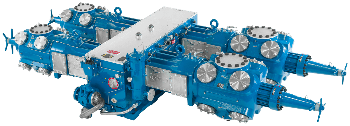 Figure 1. Ariel JGC/4 Representation
Table 2: Unit Operating Conditions
| Throw | 1 | 2 | 3 | 4 |
|---|---|---|---|---|
| Stage of Compression | 3 | Blank | 2 | 1 |
| Suction Pressure, psig | 450 | NA | 215 | 92 |
| Discharge Pressure, psig | 915 | NA | 460 | 220 |
| RPM | 1000 RPM | |||
| Specific Gravity | .59 | |||
| Application | Gas Gathering | |||
| Normal Lube Rates | Odd Side – 15 sec (22.5 pints/day) Even Side – 10 sec (26 pints/day) | |||
| Target Lube Rates (50% of Normal) | Odd Side – 30 sec (11.2 pints/day) Even Side – 20 sec (13 pints/day | |||
Executive Summary
In an effort of continuous product improvement and data gathering, Ariel worked alongside one of its end users to reduce lubrication being used in the force feed lubrication system on one of their gas gathering compressors. The target lubrication rate was to be 50% of normal lube rates recommended by Ariel at the time of the initial compressor sizing.
Regular inspections at predetermined intervals were performed to monitor packing leakage, piston rod diameters and lubrication quality on all wear parts. All wear components were inspected and measured to identify any accelerated wear. No abnormal wear was found and most components measured to be within wear limits if not within Ariel manufacturing tolerances. The inspection intervals led to successfully reaching the 50% target lube reduction. The test was concluded after the final inspection and the unit was put back online, continuing to run at the 50% lubrication reduction.
Testing Discussion
New Ariel Ultra-Low Emissions Packings (B-7147, B-7109) were installed during a 50,000 hour overhaul. Also at this point, an inspection of the cylinders, pistons, piston rods and packing was done to get a baseline understanding of how the force feed lubrication was faring in this application. The inspection revealed that all components fed by the force feed lubrication system looked to be generously coated in oil (Figure 2, 3). Based on this observation of grossly over-lubricated system, initial 10% reductions were bypassed and the lubrication rates were cut 30% as the first reduction.
After 658 hours runtime, another inspection was performed to identify any abnormal wear, packing leakage and to use the cigarette paper test to identify lubrication quality in the cylinder bores. During the inspection, packing leakage was non-existent on all stages. Each piston rod OD was measured in the packing area to monitor any wear. The piston rods were as new and the original crosshatching put in at the time of installation was still evident. The cigarette paper tests on each stage still showed that the cylinders were over-lubricated. Based on this information, lubrication rates were reduced another 10% to an overall 40% reduction from design.
After another 988 hours, the unit was inspected once again per the test plan with inspections for packing leakage, piston rod wear and cylinder bore lubrication quality. All inspections resulted in exceptional results with no measured packing leakage, no piston rod wear and slightly over-lubricated cylinder bores. Based on this inspection, lubrication rates were reduced another 10% to an overall 50% reduction from original design.
After another 1137 hours, for a total of 4655 hours since overhaul, the unit was inspected again per the test plan. The results were once again exceptional with no measurable packing leakage and no measurable wear on the piston rods. This time, the 1st and 2nd stage cylinder bores showed slight over-lubrication but the 3rd stage cylinder cigarette paper test showed that the lubrication was perfect for that stage. The 1st cigarette paper was soaked through but the 2nd paper was not. At this point, the 50% reduction goal was met. Therefore no further reductions in lubrication were made.
To ensure acceptable service life of the compressor components, the unit was again inspected after another 2167 hours for a total of 6822 hours since the overhaul. The unit exhibited the same characteristics as the previous inspection with no measurable packing leakage, similar results to the cigarette paper tests and “as new” piston rods. It was decided at this point to wait until closer to the 8000 hour mark at the 50% reduction to do the final inspection.
After 8668 hours since the overhaul and running at 50% reduction for 7022 hours, the unit was disassembled to inspect for cylinder bore wear, piston rod/piston wear, packing leakage and lubrication quality on all wear components. Packings exhibited no measurable leakage.
Cylinder bores measured to be well within wear limits and in most cases, within manufacturing tolerances. Piston rods were in “as new” condition and did not exhibit any wear through the test. Piston ring groove widths were consistent with the age of the parts and did not show any appreciable difference from original measurements at the start of the test. Lubrication quality on cylinders and piston rods was similar to previous inspections and passed the cigarette paper test (Figure 4).
Conclusion
Final inspection results revealed reducing lubrication rates by 50% did not accelerate wear or impact packing leakage. One could reasonably assume a similar or at least a significant reduction could be achieved with sister equipment having the same application and gas composition.
Cylinder Lube Test Paper Photos
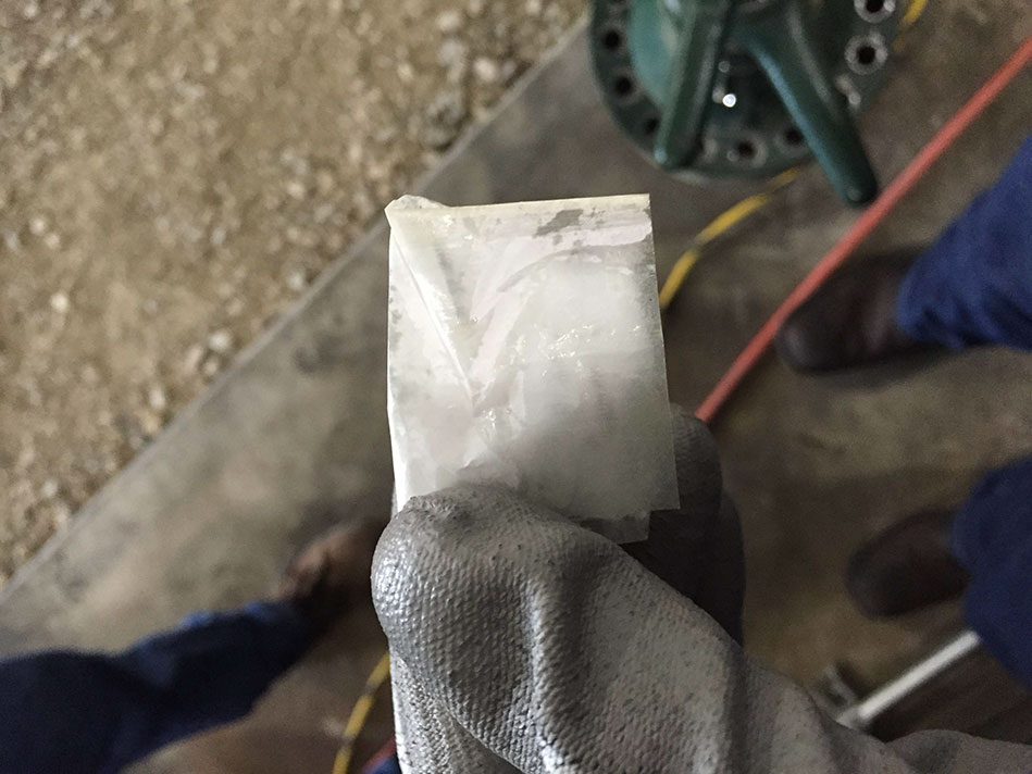 Figure 2: 3rd stage Throw #1 - 1st sheet of cigarette paper soaked completely through with oil. This was at beginning of test with normal lube rates.
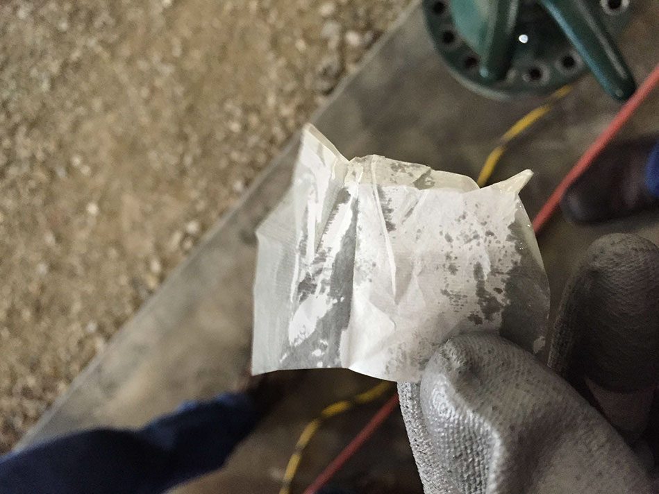 Figure 3: 3rd stage Throw #1 - 1st sheet of cigarette paper soaked completely through with oil. This was at beginning of test with normal lube rates.
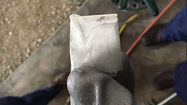
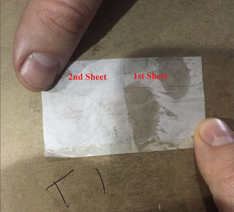 Figure 4: 3rd stage Throw #1 after 7022 hours running at 50% reduction. Oil soaked through 1st sheet, light marking on 2nd sheet. This is representative of an adequately lubricated cylinder