Reciprocating Compressors and the Hydrogen Economy
This paper will describe the "new" applications, including summarizing the operating conditions and the compressor requirements, along with some of the projects being considered.
This article was originally published at the 13th EFRC Conference by Ben Williams, Specialist – Process Sales and Market Development.
13th EFRC Conference September 19th – 21st, 2023, Zagreb, Croatia
Abstract:
The global push for decarbonization and decreased greenhouse gas (GHG) emissions will require a significant amount of hydrogen. Green hydrogen (hydrogen produced by the electrolysis of water using only renewable energy sources, such as wind and solar), is perceived by some as the best source of hydrogen needed to meet current decarbonization goals. While this may or may not be true, increased hydrogen production will require additional hydrogen compressors. While multiple compressor types are used for hydrogen, this paper will focus on reciprocating piston-type compressors.
Reciprocating compressors have been used in hydrogen service for years, primarily in the refinery and petrochemical industries. Recently, companies have been trying to determine what is required for the energy transition and how they can participate. Companies have come up with several "new" hydrogen applications. These new applications, such as hydrogen storage, hydrogen mobility, and hydrogen blending (with natural gas) will have different requirements for hydrogen compression than have been typical for refinery and petrochemical applications.
This paper will describe the "new" applications, including summarizing the operating conditions and the compressor requirements, along with some of the projects being considered. These can be complex applications and because of that, some users are willing to operate outside of the typical hydrogen operational limits that have been used for years in the refinery and petrochemical industries.
Gas cleanliness is crucial for these hydrogen applications so the majority of them are non-lubricated. Non-lubricated compressors do not use oil for cylinder lubrication, these compressors typically use „self-lubricating“ materials. The decision to use lubricated or non-lubricated cylinders, along with the source of the hydrogen, whether from an alkaline electrolyzer or a PEM electrolyzer, will determine the design of the compressor.
If it proceeds as expected, the Hydrogen Economy will be an opportunity for reciprocating compressors to shine and we should all look forward to seeing where things go from here.
1. Introduction
Reciprocating compressors, both with lubricated and non-lubricated cylinders (if within OEM discharge pressure limits), have been used in hydrogen service for decades, primarily in the refining, petrochemical, and industrial gas industries. Among the many hydrogen applications typical to these industries are hydrogen production, syngas, desulphurization (H2 Makeup and Recycle), and tail gas compression. Other non-traditional hydrogen applications include hydrogen transmission via pipeline and hydrogen storage.
As governments around the world establish mandates regarding the goal of reducing carbon emissions to a “net zero” value. Hydrogen is considered key to this, “energy transition” and the term “Hydrogen Economy” is once again routinely being used. (The term hydrogen-based economy was first used during the 1970s by John Bockris.1) To meet the decarbonization goals, significant amounts of hydrogen and hydrogen compression will be required
Green hydrogen is the focal point of the energy transition. Producing hydrogen using electrolysis, powered by renewable energy sources, such as wind and solar is considered by many to be the only way to meet the Net-Zero carbon goal. That remains to be seen.
Renewable hydrogen applications will include those applications mentioned above, as well as hydrogen fueling. The compressors used for these applications will depend on the source of renewable hydrogen, whether it be an alkaline or PEM electrolyzer or a tube trailer.
The design of the compressors will also be determined by whether or not the End User applies the traditional operating limits of API 618 and ISO 13707 or is willing to “stretch” these limits to reduce the initial compressor cost or the overall Total Cost of Ownership (TCO).
The goal of this paper is to discuss design considerations for reciprocating hydrogen compressors both in the “traditional” and renewable applications, typical operating conditions for both, and how expectations and operating limits may differ between the two.
2. Hydrogen Applications
This section will discuss the typical hydrogen applications, as well as some “new” applications that are being considered as part of the energy transition.
Note, although almost half of the hydrogen produced today is used for the production of ammonia (NH3), the compression of ammonia is very specialized and will not be addressed herein, except to say liquid ammonia is one of the numerous means of transporting hydrogen under consideration at this time.
2.1 Hydrogen Production
Hydrogen is the most abundant element in the universe, but due to its level of reactivity and chemical properties, hydrogen is primarily found as part of a compound. The primary compounds containing hydrogen are water and hydrocarbons. There are several processes used to separate the hydrogen from these compounds, including steam methane reforming and electrolysis.
2.1.1 Steam Methane Reforming
Approximately 95% of the hydrogen produced today comes from the reforming of natural gas by the steam methane reforming (SMR) process. Reacting natural gas with steam at high temperatures (approximately 600-1000 degrees C) produces hydrogen and carbon monoxide (CO). After undergoing a shift conversion process, the carbon monoxide and water produce hydrogen and carbon dioxide (CO2).
The SMR hydrogen is sent to a pressure swing adsorber (PSA) system which cleans the hydrogen. Typical PSA hydrogen has a purity of 99.9999% pure. The pure hydrogen out of a PSA is sent to the hydrogen product compressor with discharge pressures ranging from approximately 34 to 100 Bar, depending on the plant design.
Because CO2 is formed in the steam methane reforming process, this is sometimes referred to as “gray hydrogen” If CO2 capture is included in the process, this is considered by some as “blue hydrogen”.
A steam methane reformer unit located near Chicago, IL, USA is shown in Figure 1.
The steam methane reforming process involves multiple gas streams, each of which may require compression. These include natural gas feed, fuel gas, hydrogen product (from the outlet of the PSA), and tail gas.
2.1.2 Electrolysis
Electrolysis is the process of separating water into hydrogen and oxygen using electricity. If the electricity used by the electrolyzer comes from a renewable source, such as wind or solar power, the hydrogen produced is considered “green hydrogen”.
There are multiple types of electrolyzers, including Alkaline, Proton Exchange Membrane (PEM), or Solid Oxide. The most commonly discussed and the types covered herein are the Alkaline and PEM electrolyzers. The electrolyzer process has a significant impact on the hydrogen compressor selection.
The alkaline electrolysis process was discovered over 200 years ago. The basic process involves an anode and a cathode with hydroxide (OH-) ions passing from the cathode to the anode through an electrolytic solution, such as potassium hydroxide. Hydrogen is produced on the cathode side and oxygen on the anode side. Figure 2 shows the basic principle of an alkaline electrolyzer.
The typical alkaline electrolyzer produces hydrogen at or slightly above atmospheric pressure (1.01 BarA). Conversely, a Proton Exchange Membrane (PEM) electrolyzer can discharge between 8 and 30 BarA.
PEM electrolysis uses an anode, a cathode, and a membrane as the electrolyte. Water is “split” on the anode side and the hydrogen ions pass through the membrane to the cathode side. Figure 3 shows a schematic of the PEM electrolysis process.
The discharge pressure produced by the electrolyzer determines the suction pressure for the compression system. For a given application, hydrogen produced from a PEM electrolyzer will have a significantly reduced number of stages than that of alkaline electrolyzer hydrogen.
The following example shows how the electrolyzer process impacts the compressor design for a hydrogen application requiring a discharge pressure of 200 BarA and delivering 50 kg/hr.
Using OEM reciprocating compressor software to select a compressor based on the above parameters and to prevent exceeding the API 618 discharge temperature limit of 135o C (275o F), the following compressor designs were selected. These are based on one reciprocating compressor manufacturer’s product line-up.
- Alkaline Electrolyzer – 1.01 BarA electrolyzer outlet pressure.
A six-throw compressor with eight stages of compression is required. 129 kW is needed. (See Figure 4)
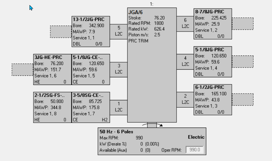 Figure 4 – Six throw, eight-stage compressor selection5
- PEM Electrolyzer – 25 BarA electrolyzer outlet pressure.
A two-throw compressor with three stages of compression is required. 54 kW needed. (See Figure 5.)
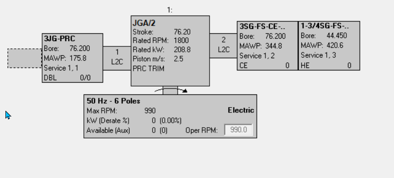 Figure 5 – Two throw, three-stage compressor selection6
The low discharge pressure from an alkaline electrolyzer will often require larger cylinders to meet the capacity requirements of the application. Depending on the application, it may require a series of compressors to reach the required discharge pressure. This depends on the cylinder size, compressor stroke and rod load limits, and the number of compressor crankshaft throws available. The number of throws depends on the manufacturer and varies from one to ten.
As you can see, the type of electrolyzer used has a significant impact on the compressor selection.
2.2 Hydrogen Desulfurization
The most common use of hydrogen in a refinery is in the desulfurization of fuels. Figure 6 shows a schematic of the desulfurization process.
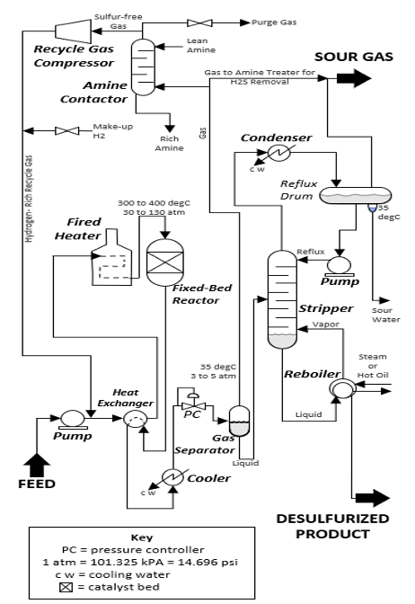 Figure 6: Desulfurization Process of Liquid Fuels7
Sulfur is removed from the liquid fuel(s) by reacting it with hydrogen in catalytic vessels at high temperatures and pressures. The process produces low or ultra-low sulfur fuels. The sulfur-rich gas is sent to an amine contactor which removes most of the sulfur. The “cleaned” recycle stream is compressed and makeup hydrogen is added to the system and the desulfurization process continues. The two hydrogen services (streams) involved in this process, hydrogen makeup and recycle may be handed with individual compressors or as a multi-service compressor with each stream independent of the other.
Typically, the discharge pressures for the hydrogen makeup and recycle services are similar, however, actual conditions depend on the process license used and the size of the refinery.
Several renewable hydrogen fuel facilities are under consideration and although they may be smaller in scale, these facilities will require similar desulfurization processes and therefore hydrogen compression.
2.3 Hydrogen Storage
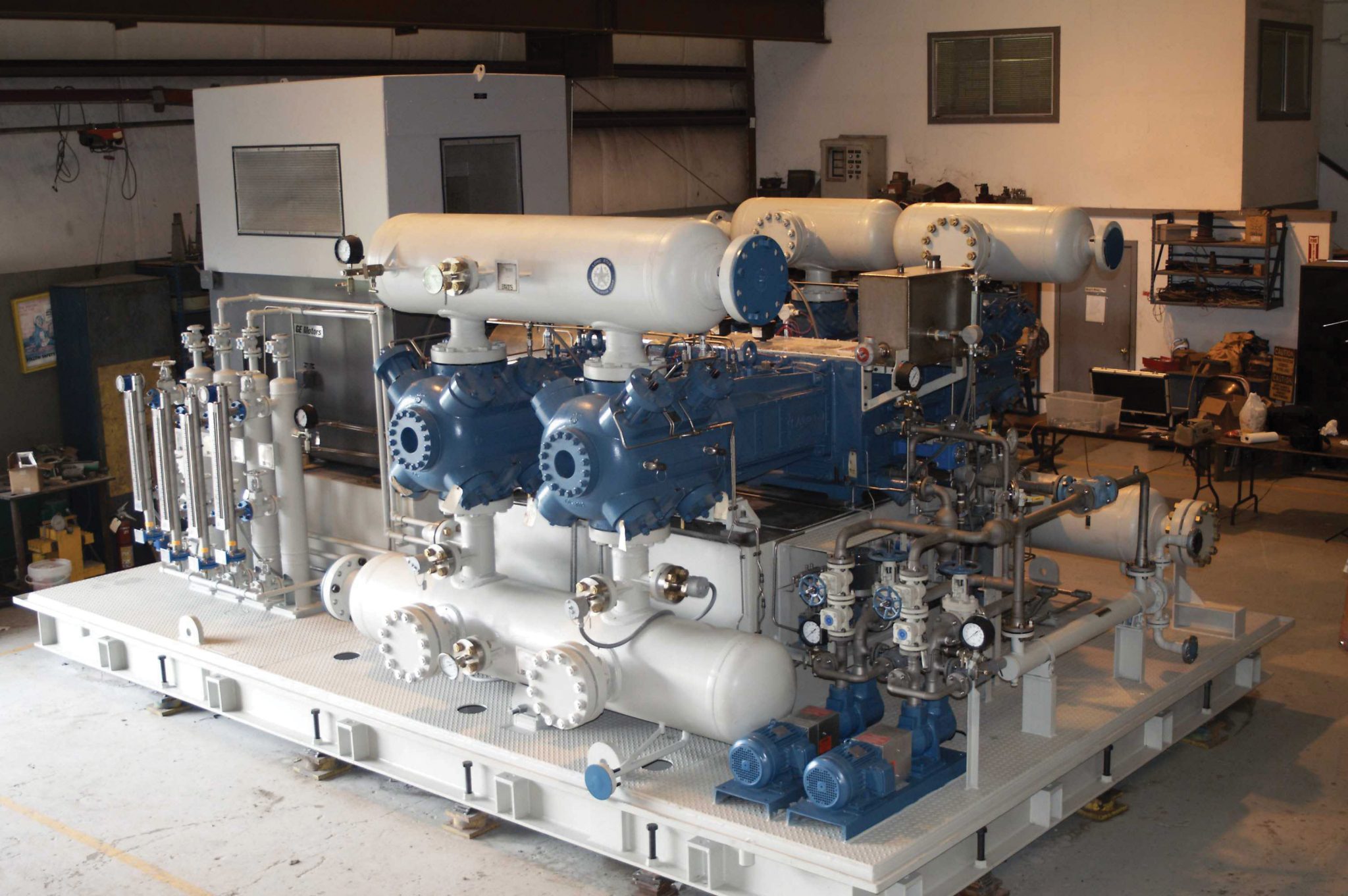
Hydrogen gas is typically stored in tanks, vessels, or underground salt caverns. Currently, there are four operational underground hydrogen storage (UHS) facilities in the world; three in the United States and one in the United Kingdom. The US facilities are used to supplement the hydrogen supply to a petrochemical plant and industrial gas hydrogen pipelines. The U.K. facility stores hydrogen for turbine generator use during peak electricity demand periods. Figure 7 shows a reciprocating compressor at a UHS facility in Texas, USA.
There are a number of pilot projects involving underground hydrogen storage under consideration.
Current underground hydrogen storage facilities operate at pressures between 45 and 200 BarA. Inquiries for renewable underground hydrogen storage pressures of up to 350 BarA have been received. The majority of compressors used in hydrogen storage at these pressures use lubricated cylinders. Typically. non-lubricated compressors will have lower discharge pressure ratings.
Hydrogen is also stored and transported in tube trailers. This has been relatively commonplace for years; however, the use of tube trailers will likely increase to transport renewable hydrogen from its production location to where it is needed. This application is also known as a “virtual pipeline”
The hydrogen storage pressure in tube trailers depends on the type of storage tubes used. Figure 8 shows a typical hydrogen tube trailer arrangement.
Hydrogen tube trailers are classified based on the materials of construction and the storage pressure.10
Type I (Type 1) Older steel tube trailers are a simple design and are limited to less than 200 BarA but newer Type IV (Type 4) hydrogen tubes are constructed from composite materials and wrapped in carbon fiber. These lighter tubes are expected to be used for hydrogen mobility applications and the tube trailers will be rated for greater than 500 BarA.
Compressors are needed to fill the tube trailers and compress the tube trailer’s discharge to the required hydrogen fueling pressure.
2.4 Hydrogen Pipeline Applications
Currently, there are over 5,000 km of operational hydrogen pipelines worldwide; approximately 2600 km are in the United States and 2000 km in Europe.9 Hydrogen pipelines operate at pressures ranging from 45 to 100 BarA.
The European Hydrogen Backbone (www.EHB.eu) project continues plans to add additional renewable hydrogen infrastructure, including pipelines and storage facilities, for decarbonization. This will include the construction of new hydrogen pipelines and when possible, converting existing natural gas pipelines to hydrogen.
Another pipeline application that has drawn quite a bit of attention, primarily in North America, is the blending of hydrogen with natural gas in existing pipelines. The primary reason for doing this is to reduce greenhouse gas (GHG) emissions.
The amount of hydrogen that can be added to an operating natural gas pipeline is still being determined. Although some inquiries may mention blending hydrogen concentrations of 50% or more to the existing natural gas stream, most projects moving forward with less than 20% added hydrogen.
Regarding the reciprocating compressors used for hydrogen blending applications, any new compressor will be designed specifically for hydrogen service. However, existing natural gas pipeline compressors used in hydrogen blending applications must now be suitable for lower mole-weight gas.
The following is an example of the impact on an existing lubricated, natural gas pipeline compressor (Figure 9) when 30% hydrogen is mixed into the gas stream (Figure 10). For simplicity, have assumed a direct swap of hydrogen and methane from the original gas composition.
Existing Compressor
30% Hydrogen blended into the gas stream (30% methane removed)
As expected the gas is now lighter and mass flow is reduced. Additionally, the ratio of specific heat (“n-value’) has increased, therefore the discharge temperature has also increased.
For this example, the compressor valves should be reviewed to determine whether they are still suitable for the lighter gas. As for the compressor itself, no material changes would be required, however, the compressor system (package) should be evaluated to determine whether the system components are suitable for the lighter gas. The lighter gas may also impact gas pulsations and a new pulsation study should be performed to ensure no changes to piping or vessels are needed.
2.5 Hydrogen Fueling
According to the International Energy Agency (IEA), in there are currently 56,000 hydrogen fuel cell electric vehicles (FCEV) on the road today. These vehicles require fueling with hydrogen. Figure 11 shows a chart from 2021 comparing the distribution of hydrogen fuel cell electric vehicles to the number of available hydrogen fueling stations.
A search of the internet shows a number of reports that have been written about the future of hydrogen FCEV and the majority of them predict a sharp increase in the number of vehicles. One such study by Precedence Research (https://www.precedenceresearch.com/hydrogen-fuel-cells-market) predicts the hydrogen FCEV market to be over $130 billion USD by the year 2030. This will require a significant number of hydrogen fueling stations.
Hydrogen fueling pressures will vary depending on the manufacturer or the application, whether it be cars, light-duty trucks, buses, or long-haul over-the-road trucks. Typical pressures vary from 350 to 1000 Bar.
Although there are fueling stations that use lubricated compressors with coalescing or oil removal systems downstream of the compressor; hydrogen fueling compressors are normally non-lube. Non-lube means that oil is only supplied to the running gear. Lubricating oil is not supplied for the cylinder or packing. This is to prevent fouling of the vehicle’s fuel cells. According to ISO 14687 (Hydrogen Fuel Quality – Product Specification), The typical hydrogen purity requirement of an H2 fueling dispenser is 99.97%.
Depending on the volume of hydrogen needed and the discharge pressure required, it is not uncommon to use a non-lubricated reciprocating piston compressor feeding into a diaphragm compressor or hydraulic intensifier. There are reciprocating compressor systems being developed that will reach higher pressures with non-lubricated compressor cylinders.
Design standards for hydrogen fueling compressors, as well as other renewable hydrogen compressors, are detailed in the following section.
3. Traditional vs. Renewable Hydrogen Compressors
API 618 and ISO 13707 are the most commonly referenced standards for hydrogen compressors used in the refinery, petrochemical, and industrial gas sectors. These standards are guidelines for compressors and system components to achieve three years of uninterrupted service and a service life of 20 years.
Due to the similarity of the applications, expectations would be that API 618 or ISO 13707 would be required for compressors used in renewable hydrogen service. However, based on inquiries received for renewable hydrogen compressors, that is not always the case. In a large number of cases, we have seen customers who are willing to forgo those standards and do not require the longer runtimes associated with each.
3.1 Achieving longer runtimes
Among the key design features described in API 618 and ISO 13707 that contribute to longer compressor runtimes are:
Piston speed – Piston speed affects the non-metallic wear parts that rub, such as piston rings, wear bands, and packing. Lower piston speeds promote longer non-metallic wear part life.
Discharge temperature – The maximum discharge temperature for hydrogen-rich applications is 135 degrees C (275 degrees F). Typical TFE-based wear parts are suitable for operating up to 175 degrees C (350 degrees F). The lower the discharge temperature, the better it is for non-metallic wear part life. Oil viscosities are higher with lower discharge temperatures; as temperature increases, the oil viscosity decreases.
Wear band loading – Wear band loading is the force (bearing load) due to the piston weight and half of the piston rod weight divided by the projected area of a 120-degree arc of the wear bands. API 618 and ISO 13707 limit this to 0.035 N/mm2 (5 PSI) for non-lubricated units and 0.070 N/mm2 (10 PSI) for lubricated cylinders. Reduced wear band loading leads to longer wear part life.
Cylinder lubrication – It is crucial to select the proper type and amount of lubricating oil, based on the gas composition and compressor operating conditions. It is also important to remember that more oil is not always better. Divider blocks, pump-to-point, or a combination of both are commonly used in cylinder lubrication systems.
NOTE – Non-lubricated cylinders are also used in these “traditional” hydrogen applications, where suitable.
3.2 A Different Viewpoint
As previously mentioned, based on inquiries received for renewable hydrogen applications, API 618 or ISO 13707 are not always required. In many cases, the end user is not the typical process compressor customer and is open to taking a new approach to these applications.
With this new approach to renewable hydrogen compressors, the design may include:
Non-lubricated cylinders - Many of the renewable hydrogen compressors are non-lube and therefore 3 years is not expected. Hydrogen fueling compressors are normally non-lubricated. When discussing current hydrogen fueling compressors, whether reciprocating, diaphragm, hydraulic, or a combination, with several End Users, expectations of wear part life is less than a year.
Higher Discharge Temperatures - These customers are often willing to accept discharge temperatures greater than the 135o C (275o F) limit in API 618. The API 618 limit was established years ago with the goal of achieving three years between shutdowns. It is interesting to note that in a lubricated hydrogen compressor, the non-metallic wear parts (piston rings, packing, and wear bands) used are often the same materials used for other lubricated compressors in different applications, to which the 135o C (275o F) limit does not apply. The majority of these non-metallic materials are suitable for temperatures up to 175o C (350o F). To illustrate the point about discharge temperature, using the alkaline electrolyzer conditions shown earlier in this document, if the discharge temperature was allowed to exceed the API 618 limit but stay under 150o C (300o F) only seven stages would be required, rather than 8. This reduces the capital cost (CAPEX) of the compressor system. This combined with the cost of operation (OPEX), determines the Total Cost of Ownership (TCO) which is often the determining factor in the compressor selection.
Higher rotating speeds – A higher rotating speed results in smaller cylinders which decrease the size of the compressor package or system. Attention must be paid to the compressor valve design with the higher rotating speeds. Rotating speed and valve lift affect the impact velocity of the valve sealing elements.
It is important to note that in those cases where API 618 or ISO 13707 are not required, safety is not compromised. Safety is always paramount regardless of the reciprocating compressor application. An example of this is hydrogen fueling compressor systems.
Currently, the primary standard used for hydrogen fueling compressor systems is the National Fire Protection Standard (NFPA) 2 Hydrogen Technologies Code. This standard is designed to provide safety rules for hydrogen generation, installation, storage, piping, and handling of gaseous and liquid hydrogen.8 At least one organization, ISO, is in the process of writing a standard for hydrogen fueling, including a section on hydrogen fueling compressors.
4. Conclusion
Although global decarbonization is universally accepted, there are questions about the timeline and the availability of resources to see it through. The hydrogen economy has been predicted before and went nowhere. What is different this time is that governments have issued hydrogen strategies and mandates to meet Net Zero Carbon initiatives by 2050 or earlier in some cases. A lot of money is being spent on new and existing infrastructure to enable transporting of hydrogen from the renewable source to the point of use. With this will come a need for hydrogen compression.
The compressors needed for renewable hydrogen may not be the typical refinery or petrochemical hydrogen compressors used in the past. End users will decide whether they can accept less conservative design features such as higher temperatures and speeds to reduce overall TCO. Whatever their decision, we can expect increased demand for hydrogen and hydrogen compressors as we move forward with the goal of global decarbonization.
5. Acknowledgements
Special thanks to Ms. Kaley R. Coss (Ariel Corporation – Application Engineer) for her assistance with the review and editing of this document.
References
U. Bardi, “A concise history of the concept of “Hydrogen Economy.’” Resilience, 21 May 2021. https://www.resilience.org/stories/2021-05-21/a-concise-history-of-the-concept-of-hydrogen-economy/ (accessed 13 March 2023).
Steam methane reforming unit in a facility near Chicago, IL USA. Ariel Corporation. [Photo].
N. Ironside, “Electrolysis: The Backbone of the Green Transition.” COWI, 28 April 2022. https://www.cowi.com/insights/electrolysis-the-backbone-of-the-green-transition (accessed 13 March 2023).
N. Ironside, “Electrolysis: The Backbone of the Green Transition.” COWI, 28 April 2022. https://www.cowi.com/insights/electrolysis-the-backbone-of-the-green-transition (accessed 13 March 2023).
Ariel Performance Software
Ariel Performance Software
The Role of Hydrogen in Removing Sulfur from Liquid Fuels. Praxair (Now Linde), 1 March 2017. [Online] Available: https://www.linde.com/-/media/linde/merger/documents/sustainable-development/the-role-of-hydrogen-in-removing-sulfur-from-liquid-fuels-w-disclaimer-r1.pdf?la=en#:~:text=Hydrogen%20is%20a%20proven%20solution,tons%20per%20year%20of%20SO2. (accessed 13 March 2023).
Reciprocating compressor package at an underground hydrogen storage facility in Texas, USA. Ariel Corporation. [Photo].
“Hydrogen Tank – FAQ Guide.” Hyfinder, 15 January 2023. https://hyfindr.com/hydrogen-tank/ (accessed 13 March 2023).
Hydrogen tube trailer. https://www.energy.gov/eere/fuelcells/hydrogen-tube-trailers
Ariel Performance Software
Ariel Performance Software
J. M. Bermudez, S. Evangelopoulou, F. Pavan. “Hydrogen Supply.” IEA, September 2022. https://www.iea.org/reports/hydrogen-supply (accessed 13 March 2023).
NFPA Hydrogen Technologies Code, National Fire Protection Association, 2023. [Online] Available: https://www.nfpa.org/codes-and-standards/all-codes-and-standards/list-of-codes-and-standards/detail?code=2 (accessed 13 March 2023).