Non-lubricated Moderate Speed Reciprocating Compressors in a Hydrogen Plant

Abstract:
In 2007 Air Liquide made the decision to purchase and install packaged, non-lubricated, moderate speed compressors for the hydrogen and natural gas feed services in a hydrogen plant supplying a refinery in South America. The compressors have been operating successfully for over two years. This case study will include a description of the compressor selections and details on the operational history.
1 - Introduction
Since the early 1990’s; emission regulations throughout the world have led to increased demand for hydrogen. That is because hydrogen is required for many desulphurization processes. Industrial gas companies have constructed a number of Hydrogen plants throughout the world to meet the demands of the refining and petrochemical industries.
The majority of reciprocating compressors used in these hydrogen plants have been lubricated, long-stroke, slow speed types. This is due to historical preference and the perception that these are the most reliable compressors available. It should be noted that other types of reciprocating compressors have also been used successfully in these facilities. These include vertical compressors and horizontal, short stroke, moderate speed types.
Although lubricated compressors are the most common type used in these facilities, there are times that the design of the hydrogen plant or its components cannot tolerate oil carryover in the gas stream. In those cases, the decision must be made whether to use a lubricated compressor with a downstream coalescing (oil removal) system or a non-lubricated (dry piston) compressor.
When determining lubricated vs. non-lubricated compressors, among the items that need to be considered are the impact of oil downstream of the compressor, initial and life cycle cost, and frequency of required maintenance. Typically non-lubricated compressors will have a higher initial capital cost due to the higher cost of wear part materials. Non-lubricated compressors typically require more frequent maintenance than a lubricated compressor.
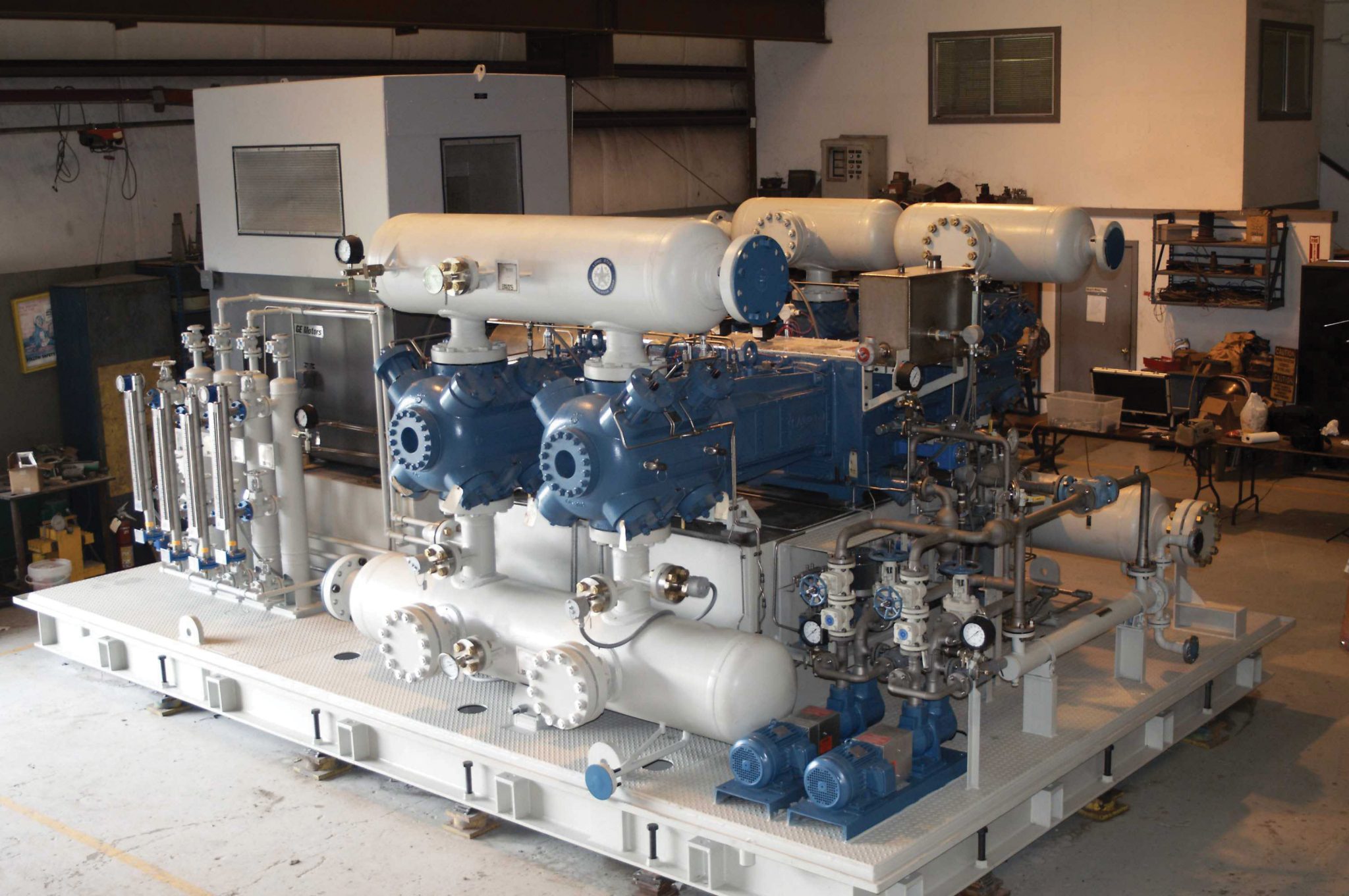
In 2007, Air Liquide made the decision to purchase packaged, non-lubricated, horizontal, balanced opposed, short stroke, moderate speed reciprocating compressors for the natural gas feed and hydrogen product services at a new hydrogen plant they were constructing in Campana, Argentina.
The hydrogen plant went on-line in November 2009. This paper describes the compressor selections, provides a brief overview of their design characteristics, and summarizes their operational history.
2 - Air Liquide Campana
- 2.1 - Hydrogen Production Unit
Air Liquide built a new hydrogen unit (steam methane reformer technology) in Campana, Buenos Aires, Argentina. The unit supplies hydrogen and steam to the Esso Petrolera Argentina refinery for use in the production of gasoline.
Prior to this project; Air Liquide would typically purchase vertical, slow speed compressors for this type of facility. The decision to purchase moderate speed, short stroke compressors for the Campana project was based on delivery, compact packaging, and capital cost. Spare parts availability and references for similar applications also contributed to the decision to purchase moderate speed reciprocating compressors.
The decision to use non-lubricated compressors for both the natural gas feed and hydrogen product services was based on differing requirements. Primarily; the natural gas feed service required non-lubricated compressors to prevent oil contamination of the Air Liquide process and process equipment. The hydrogen compressors needed to be non-lubricated due to Air Liquide's customer requirements.
 Campana, Buenos Aires, Argentina
2.2 - Compressor Requirements
2.2.1 - Natural Gas Feed
P suction (BarA) 11 P discharge (BarA) 41 Gas specific gravity 0.5727 Capacity required (Nm3/hr.) 6800 Figure 2 Feed gas compression requirements
2.2.2 - Hydrogen Product
P suction (BarA) 28 P discharge (BarA) 54 Gas specific gravity 0.0741 Capacity required (Nm3/hr.) 15400 Figure 3 Hydrogen compression requirements
3 - Compressor Selections
Air Liquide purchased two 100% capacity, non-lubricated, non-cooled, short stroke, moderate speed, electric motor driven reciprocating compressors for each service. (Typically, Air Liquide will purchase either two 100% or three 50% units for their hydrogen plants.)
Following are a brief description of the compressor selections and details on the calculated performance of each.
3.1 - Natural Gas Feed
Non-lubricated, short stroke, moderate speed, two stage, two throw compressor driven by a 500 kW, 750 RPM squirrel cage induction motor.
Cylinder Data: Stage 1 Stage 2 Cylinder bore dia., mm 358.78 244.48 Cylinder MAWP, BarG 56.2 87.6 Compressor Performance Calculations
Stage 1 2 Calculated flow Nm3/hr. 6876 6860 Gas specific gravity (S.G.) 0.5727 0.5726 Ratio of Specific Heat “N”) cc 1.2864 Suction pressure (BarA) 11 21.72 Suction temperature (C) 37.1 40 Discharge pressure (BarA) 22.15 41 Discharge temperature (C) 96 96 3.2 - Hydrogen Product
Non-lubricated, short stroke, moderate speed, two stage, two throw compressor driven by a 500 kW, 750 RPM squirrel cage induction motor.
Cylinder Data: Throw 1 Throw 2 Cylinder bore dia., mm 244.48 244.48 Cylinder MAWP, BarG 87.6 87.6 Stage 1 Calculated flow Nm3/hr. 15503 Gas specific gravity (S.G.) 0.0741 Ratio of Specific Heat “N”) 1.4047 Suction pressure (BarA) 28 Suction temperature (C) 45 Discharge pressure (BarA) 54 Discharge temperature (C) 119
4 - Compressor Design Characteristics
As noted previously, the compressor frame models are the same for both services. The following overview applies to both the natural gas feed and hydrogen product compressors; unless otherwise noted.
4.1 - Compressor Frames
- Model – JGT/2
- Compressor stroke (mm) – 114.3
- Piston rod diameter (mm) – 50.8
- Rated speed (RPM) - 1500
- Operating speed (RPM) – 744
- Average piston speed (mps) – 2.8
- Rated tension rod load (kN) – 165
- (Average calculated tension rod loads were 119 kN and 103 kN, respectively)
- API-618 Type “C” distance pieces
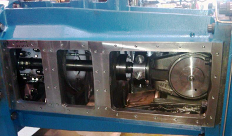 Figure 4: API-618 type “C” distance piece
4.2 - Cylinder Bodies
- Material - ASTM A395 ductile iron
- Non-cooled
- Unlined - ion-nitride hardened to approximately 57 Rc.
- Surface finish – 0.15 micro-meters
4.3 - Piston and Rod Assemblies
- Piston material - ASTM A48 Class 30 gray iron (2 piece)
- Piston rod material - Low alloy carbon steel with tungsten carbide coating
- Surface finish – 0.2 micro-meters
- Piston wear bands
- 1 piece, angle cut
- Pressure balanced
- 0.035 N/mm2 wear band loading
- Special polymer alloy for oil free service.
- Piston rings
- 1 piece angle cut
- Special polymer alloy for oil free service.
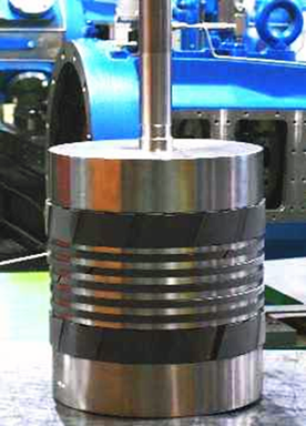 Figure 5: NL piston assembly
4.4 - Packing
Water cooled packing case- carbon steel Packing purged with nitrogen Combination of cut and uncut packing ring sets Special polymer alloy for oil free service Intermediate and wiper packing sets include buffered packing rings.
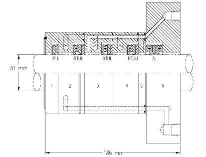 Figure 6: Pressure packing case
4.5 - Valves
- Natural gas feed compressor
- Non-metallic plate valve
- 2.59 mm lift
- Hydrogen compressor
- Non-metallic concentric ring valve
- 0.99 mm lift
- Designed for non-lubricated service
- Head end valve depressor type suction valve unloaders.
- Thermocouples for monitoring discharge valve temperatures.
- Natural gas feed compressor
5 - Operating History
The compressors are operating on a rotational basis; generally, the units are switched every six months. The natural gas compressors are run at 100% capacity; the hydrogen compressors operate at 50% load.
As of March 2012 – The plant had been in operation for approximately 18,000 hours total. The individual compressor operating hours were as follows:
- Natural gas feed
- Unit 1 – 12086 hours
- Unit 2 – 6726 hours
- Hydrogen
- Unit 1 – 9202 hours
- Unit 2 – 9334 hours
5.1 - Inspection Results
Inspections have been performed on two of the compressors; one hydrogen and one natural gas feed. Each had approximately 9,300 hours run-time at the time of the inspections.
5.1.1 - Running Gear
The running gear for both compressors was inspected, and all clearances were within specified tolerances.
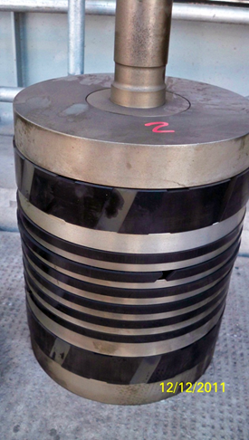 Figure 7: Campana hydrogen compressor piston after 9300 hours of operation.
5.1.2 - Cylinder Inspection Results
Visual and dimensional inspections were performed on each cylinder. A brief summary of these inspections follows:
- Piston and Piston Rod Assemblies
- Piston Rods (Nominal Dimension – 50.8 mm)
Piston rods were inspected for damage and wear. Rod diameters (as measured in Figure 8) all were acceptable; 50.76 to 50.78 mm. All piston rods were cleaned and reinstalled, with no repairs needed.
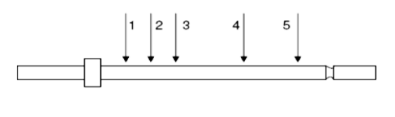 Figure 8: Piston rod inspection points
Pistons
Piston ring grooves and wear band grooves were inspected. All groove widths and depths were within new tolerance.
Piston Rings and Wear Bands
Piston ring and wear band radial thickness, side clearance, and end gaps were measured. All showed normal wear. The hydrogen compressor piston rings (PR) and wear band (WB) measurements are shown in Figure 9, along with the same measurements for the new replacement rings and wear bands.
Cylinder Bore Dimensions
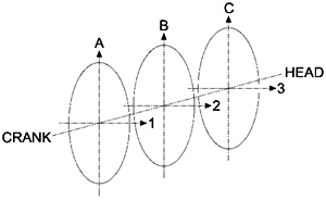 Figure 10: Cylinder bore measuring points
| Dimension (mm) | Cylinder 1 | Cylinder 2 | New |
|---|---|---|---|
| WB Radial Thickness | 8.8-9.2 | 8.8-9.2 | 9.6 |
| WB Width | 40.8 | 40.8 | 40.8 |
| WB End Gap | 10.5 | 10.5 | 7.0 |
| PR Radial Thickness | 9.3 | 9.3 | 9.3 |
| PR Width | 11.5-11.9 | 11.5-11.9 | 12.9 |
| PR End Gap | 8.0 | 8.0 | 8.0 |
Figure 9 Piston ring and wear band measurements
It is a common perception that cooled cylinders are needed for critical service machines; particularly non-lubricated types. As noted previously; the cylinders on these moderate speed compressors are non-cooled. The worn piston ring and wear band dimensions shown in Figure 9 are within the manufacturer’s acceptable range. These rings and wear bands could have been re-installed. However, as spare piston rings and wear bands were available, the decision was made to replace them.
| Dimension (mm) | NG Feed Stage 1 | NG Feed Stage 2 | Hydrogen Cylinder 1 | Hydrogen Cylinder 2 |
|---|---|---|---|---|
| A | 358.80 | 244.52 | 244.05 | 244.05 |
| 1 | 358.78 | 244.50 | 244.00 | 244.02 |
| B | 358.90 | 244.89 | 244.09 | 244.10 |
| 2 | 358.84 | 244.97 | 244.05 | 244.11 |
| C | 358.78 | 244.51 | 244.11 | 244.11 |
| 3 | 358.78 | 244.52 | 244.05 | 244.11 |
Figure 11 Cylinder bore diameters recorded during inspections
Packing Rings
The packing rings showed normal wear. However, there were some broken springs and packing rings in one of the hydrogen compressor packing cases (See Figure 12). All packing cases were cleaned up and packing rings were replaced with rings of the same material.
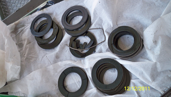 Figure 12: Packing ring set – shows broken spring and packing rings.
Valves
Due to the rotating speeds of moderate speed reciprocating compressors; a common industry concern is the number of times the compressor valves open and close; as compared to those of a longer stroke, slow speed compressor. In this case; the compressor valves are cycling at 744 times per minute. The valves for both units were inspected, and all valves looked good. The valves were re-installed in both compressors. Air Liquide plans to replace the valves at the 16,000-hour inspection.
6 - Conclusion
Moderate speed compressors have performed well in hydrogen and natural gas feed services at an Air Liquide hydrogen plant in Argentina. After 9300 hours of operation, two of the four compressors were inspected, and the cylinder wear parts (piston trim, packing, and non-metallic valve components) showed little or no wear. This can be attributed to a number of things, including clean, dry gas at the compressor suction, wear part material selection, conservative design and application, as well as reduced piston speeds.
In simple terms, piston speed affects the “rubbing parts.” Although the rotating speed is higher than “normal” for these types of applications; the short stroke, moderate speed compressors installed at Campana have very conservative piston speeds. The low piston speeds have a very positive effect on the life of the wear parts.
Although the valves in these cylinders cycle more often than what would be considered “typical” for the industry, these valves were found to be in very good condition and were reinstalled for continued use.
It is important to note that the moderate speed compressors detailed herein use non-cooled, unlined cylinders. The commonly held industry viewpoint is that cylinder cooling and liners are necessary for a successful operation; especially in those applications requiring non-lubricated compressors. However, as the inspection results described in this article show; there is an alternative design suitable for these applications.
With a conservative design and application; along with proper material selection and package design, moderate speed reciprocating compressors are very well suited for use in critical services, such as hydrogen plants.
7 - References
- Google Maps – Map of Campana, Argentina
- Dimensional data included herein was taken from Air Liquide inspection / maintenance reports dated 22 June 2011 and 27 December 2011.
Acknowledgements
- The author would like to acknowledge and thank the following people for their invaluable contribution to this paper:
- Mr. Thierry Ott – E&C Project Director - Air Liquide Engineering and Construction
- Mr. Guillermo Tear – Chief Maintenance Engineer -Air Liquide Argentina, SA
- Mr Marcelo Ledesma – Technical Service Engineer – Hoerbiger Argentina, SA
- Mr. Greg Phillippi – Director Process Mktg. & Sales – Ariel Corporation
“Non-lubricated Moderate Speed Reciprocating Compressors in a Hydrogen Plant” was written and presented by Ben Williams in Dusseldorf, Germany, at the 2012 European Forum for Reciprocating Compressors. Williams is the Process Application and Account Manager at Ariel Corporation.