Compressor Emissions Reduction Technology
Dan Hannon, Ariel Corporation
Gas leakage from reciprocating compressors can be more than a loss of product. Leakage of gas to the atmosphere can be a concern from an environmental, health and safety, and area classification perspective. Regardless of the reason, minimizing or even eliminating gas leakage is a goal of all manufacturers, operators, and owners of reciprocating compressors. There are several static and dynamic seals where leakage can occur.
This paper will discuss the areas of potential leakage and the steps that have been taken to eliminate or reduce leakage at these points from a design perspective. The focus of this is to offer an understanding of the steps the natural gas industry has already taken to reduce or control gas leakage. The topics being discussed will include:
- Gas piping connections
- Compressor cylinder valve caps
- Compressor cylinder heads
- Unloading devices
- Piston rod pressure packing
- Collection for recovery or disposal
Gas Piping Connection
The type of connections and sealing elements vary with both size and pressure rating. For the most common operating pressures in the natural gas industry, ANSI type flanges are applied. Spiral wound metallic gaskets have replaced flat face paper style gaskets long ago. The sealing capability of spiral wound gaskets will depend upon the proper flange to flange alignment. Once the piping is installed properly, leakage at these flanged joints can be eliminated. Higher pressure piping joints may have ring or lens type joint connections. Some smaller lines may be tubing with compression style fittings. Regardless of the type or size of the connection, good fit up practices must be followed. Connections must be properly aligned, avoiding undo force to draw the two mating connection together. Gas leak detection methods can be used to confirm positive sealing at piping connections. Analysis and allowance for piping growth from thermal changes will greatly help reduce forces and alignment concerns at the piping connections.
Compressor Cylinder Valve Caps
Valve caps both allow access to the compressor valves and hold the valve securely in place. Valve cap designs have evolved over the years for improved valve retention as well as improved gas sealing. In the past, valve caps were sealed to the cylinder with paper gaskets. This type of sealing required a center bolt type of adjustment to retain the valve in place. Both the paper gasket and the center bolt offered challenges to maintaining a leak-free assembly. The o-ring type valve cap replaced the older center bolt valve cap design. An o-ring is located on the outer diameter of the valve cap nose, sealing against the wall of the cylinder. Valve retention is maintained by the valve cap bolts. This o-ring seal provides a positive seal, eliminating gas leakage at the valve caps. Good maintenance practice must be followed to ensure the o-rings are replaced on a routine basis. Care must be taken to ensure the o-rings are not cut during installation.
The design of the o-ring sealing must consider compatibility with both the gas being compressed and the lubricants that will be used for the cylinder lubrication. Explosive decompression can occur in higher pressure applications and specific gas types. Explosive decompression is a blistering or rupture of the o-ring due to gas that has permeated the o-ring rapidly expanding during a blow down event. Confirmation of the o-ring materials or o-ring groove diameter will reduce this rupture.
With proper installation, the o-ring type valve cap sealing design eliminates gas leakage at this joint. Gas leakage detection can be applied to confirm.
Compressor Cylinder Heads
Cylinder heads enclose the ends of the cylinder. The head to cylinder joint is a static sealing location that will be leak-free with proper design and installation. Paper gaskets have been replaced in the cylinder to head seal design over the years with metallic ring gaskets. With proper installation and maintenance, these are gas-tight seals that offer zero leakage.
The cylinder head bolts apply the clamping force for the seal as well as the strength for the gas pressure retention. These bolts carry the gas load of the cylinder. The use of these bolts for mounting additional hardware, such as vertical supports, is to be avoided.
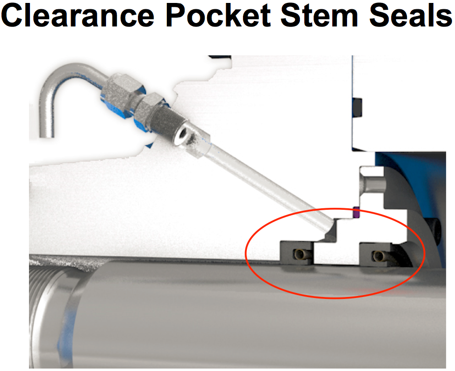
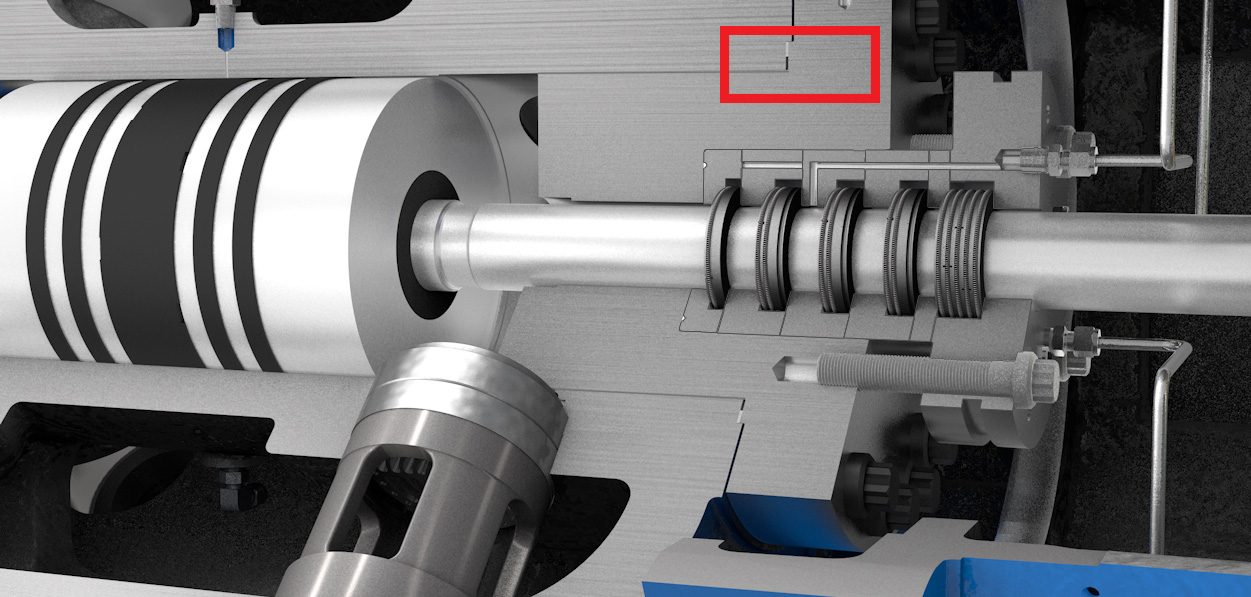
Unloading Devices
Unloading devices include head-end clearance pockets, valve unloaders, valve pockets, and head spacers. The unloading devices are used to reduce flow or power by either lowering the compression efficiency or disabling compression on an end of the cylinder. Unloading devices can be manually operated or pneumatically operated. Hydraulic and electric devices are less common.
Unloading devices will introduce an additional leakage path, at the actuation stem. The frequency of unloading can be several times per hour, or once per month. The stem seals will require a static type seal that must allow intermittent action. Stem seal designs are various and have changed over the years to offer better sealing capabilities and longer seal life. Most often, a pair of seals are installed with a telltale vent between the seals. If the first seal leaks, the vent allows the capture of the gas through a controlled vent line. With proper installation and maintenance practices, leakage at unloading device stems can be expected to be zero.
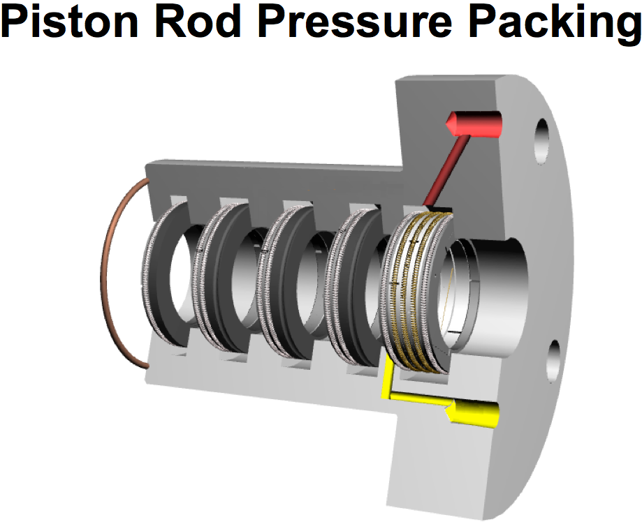
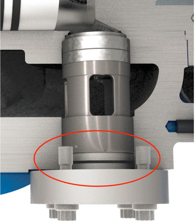
Piston Rod Pressure Packing
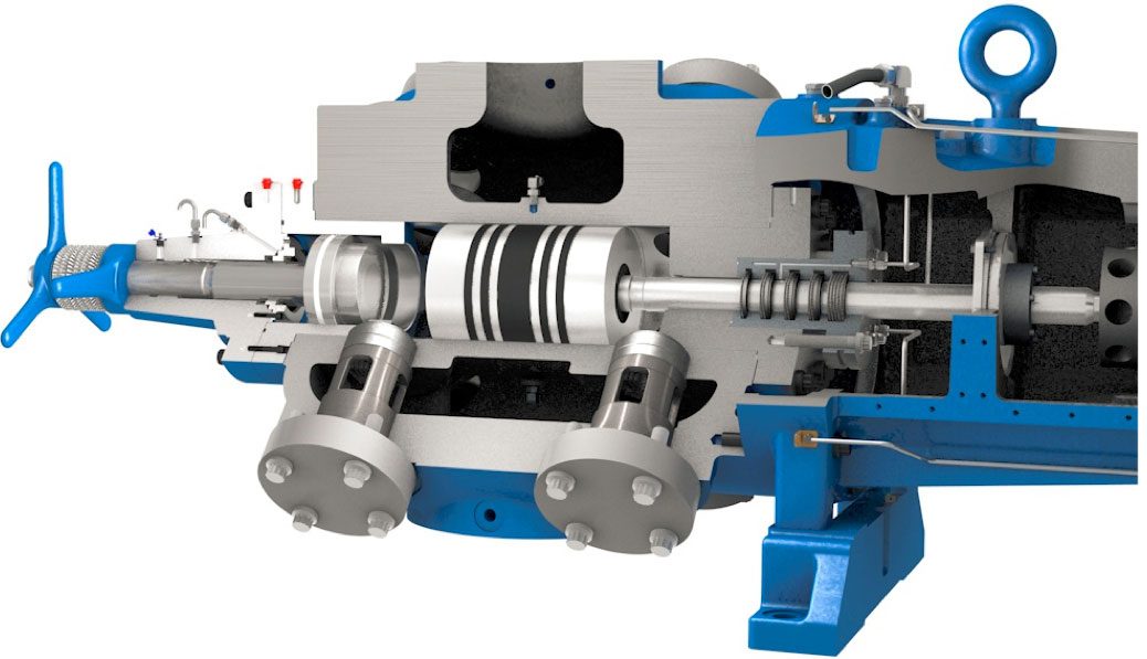
Piston rods extend through the cylinder head into the compressor frame. The piston rod moves in and out of the cylinder at average speeds of up to 1200 fpm at displacements (strokes) of 3 inches up to 8 inches on natural gas separable compressors. The pressure packing case helps seal around the piston rod. The pressure packing seals are designed to minimize gas leakage and allow routing of leakage to a safe disposal or collection point. The pressure packing is a dynamic seal, so it is expected to have gas leakage as the seals wear, and often even when installed new.
Various designs have been applied throughout the years. Some improvements address the stationary sealing surfaces, but few make major strides in addressing the main leakage path between the packing rings and the piston rod. One such recent improvement, uncut ring technology, will be discussed here.
Typical packing ring design utilizes several sets of rings in series within the packing case. These ring sets may include one to three or four rings. Rings are typically segmented, cut into three pieces, with various cut patterns. These are held together with a garter spring around the outer diameter of each ring. The cut patterns are applied to allow the ring to maintain contact with the piston rod as the rings wear. The variations in cut patterns are used to ensure the gaps of consecutive rings do not align, minimizing leakage. Two factors that contribute to the quantity of leakage over the life of the packing include leakage between the ring segments and wear at the piston rod contact. Wear life is very dependent upon the amount of debris in the gas and the heat of contact friction.
The uncut ring design is a three to four ring set with two rings typically being a segmented design and two rings being a solid or uncut design. The uncut rings maintain a very slight clearance to the piston rod. One of the solid rings may be cast iron, acting as support for the solid sealing ring. Typically, only one ring set will seal. Once worn, the next seal set will be enacted by the pressure to seal. The solid seal ring helps reduce leakage by eliminating the gaps between traditional segmented rings. When pressurized, the solid seal will enclose on the rod, offering a more effective seal.
This "loading under pressure" allows for a very tight seal, eliminating leakage that may occur with traditional segmented rings at the cut and along the piston rod from uneven wear. The results are lower piston rod to ring temperatures and lower leakage rates. Lower temperatures relate directly to longer life, longer time between maintenance.
Typical leakage rates for traditional segmented packing rings are near 0.1 to .17 scfm when the packing seals are in the new condition. Leakage rates of worn rings will increase until replaced. The typical rate for an "alarm" point in order to schedule maintenance is near 1.7 to 3.4 scfm per packing case.
Reported leakage rates for uncut ring designs have shown similar and lower leakage rates when new. Due to the lower heat of friction, the rings will wear less over time and seal longer. Leakage rates are much lower across the same number of operational hours.
Installation Sample 1
A set of (7) Ariel JGK/4 compressors (2.0 inch diameter piston rod) includes both traditional segmented and uncut technology piston rod packing rings. The uncut rings outlasted the segmented rings "by a good margin." The uncut rings were not showing leakage until one to 1-1/2 years of operation. Out of three units operating under the same conditions, with the uncut rings installed, one unit showed minimal leakage while the other two still showed no leakage after two years of operation.
Installation Sample 2
A set of (12) Ariel JGC/4 size compressors (2.5 inch diameter piston rod) with uncut ring technology installed. The first four months of operation showed measured leakage of zero scfm to 0.2 scfm per packing case. The greatest majority of measurements were zero.
Installation Sample 3
Several Ariel JGT/4 compressors (2.0 inch diameter piston rod) operating at 1400 rpm and a piston speed of 1050 fpm. Compression from 850 psi to 1130 psi
Initial installation of traditional segmented packing rings were reported to have high leakage in the new and broken in condition. Packing rings were replaced with the uncut ring configuration. Initial packing leakage was reduced dramatically.
Initial installed segmented rings showed average leakage of 1.3 scfm per packing case. Installed uncut rings showed an average leakage of 0.035 scfm per packing case. Piston rod temperatures were reduced from an average of 206 F to 190 F with the change from the segmented rings to the uncut rings.
A follow up of the installed uncut rings provided measurement data ranging from 0.0 scfm to 1.5 scfm for operating hours ranging from 12,000 hours to 18,000 hours. The majority of packing cases showed near-zero leakage in this operating hours range. The average packing leakage per packing case was 0.094 scfm, with an average operating time of just over 16,000 hours.
A final follow up occurred after six units attained 28,000 and 32,000 hours. The leakage rates on these 24 packing cases after 3-1/2 to 4 years of operation showed an excellent reduction in the typical leakage and wear rates. The average leakage rate across the 24 packing cases was 0.45 scfm, with a maximum single packing leakage rate of 2.57 scfm. 14 of the 24 cases exhibited zero measurable leakage.
Expected packing leakage for typical alarm points (time to schedule maintenance) is between 1.7 and 3.4 scfm.
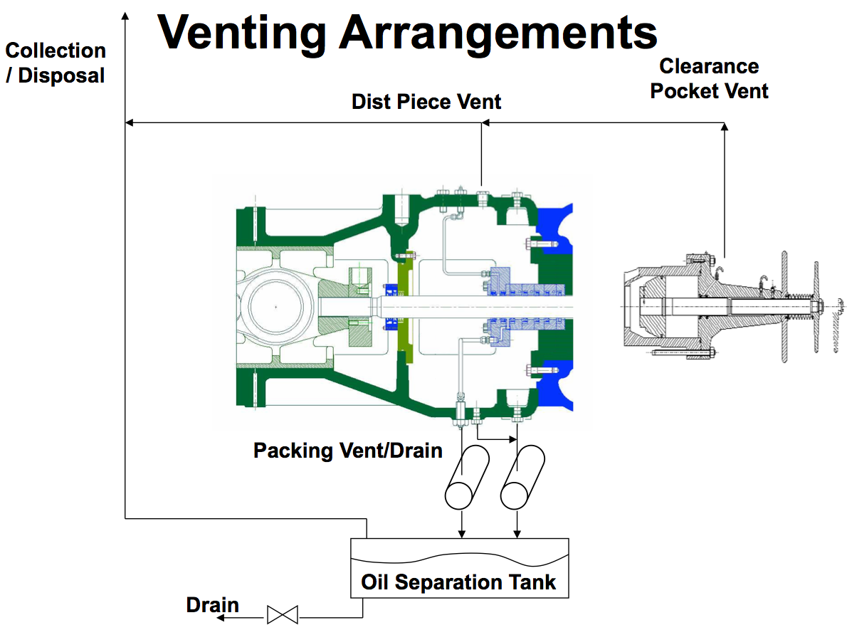
Routing Leakage for Collection or Disposal
Leakage will eventually occur regardless of the packing design installed. If the gas cannot be vented to the atmosphere due to environmental or health and safety reasons, a suitable collection system may be necessary. There are various system designs that can be employed for various levels of containment. Minimizing natural gas emissions to the atmosphere can be accomplished with reasonable efforts and methods. Eliminating emissions of lethal gas, such as hydrogen sulfide, requires a more comprehensive vent system. There are features and options that can be added to a reciprocating compressor to accommodate the level of the system needed. These include different distance piece configurations, purge gas capabilities, and various vent system layout plans. Discussions on suitable vent collection designs are included in API-618, GMRC Guidelines for High Speed Reciprocating Compressor Packages and equipment manufacturer guidelines.
Conclusion
Natural Gas and Carbon Dioxide are considered green house gasses (GHG's). The EAP has stated that an increase in green house gas emissions to our atmosphere can contribute to an overall warming of our environment. Environmental agencies have begun providing regulations on emissions of green house gasses. Currently, the pressure packing sealing on a reciprocating compressor are regulated based upon operating hours, not overall leakage. Even so, leakage reduction remains a main focus for packing seal manufacturers and reciprocating compressor manufacturers.
The reciprocating compression industry has not sat idle, allowing gas leakage to occur. Great strides have been made in reducing potential emissions. All static sealing locations have been addressed over the years and are not considered locations for emissions today. Dynamic sealing locations, such as the pressure packing case, are improving dramatically with newer ideas and designs. Leakage that does occur can be collected very effectively, for either disposal or re-use. This is a topic for much further monitoring and development.